I think I get it now. Bagby's phase extraction is supposed to look like the Phase window (delayed) response (and it kinda does have a resemblance from 10 to about 600 hz), it's not supposed to look like the SPL + Phase response. Correct?
Hi just a guy,
I'm not sure how Jeff's Excel-based software works, but I suspect that if nothing else, it assumes a direct radiator type loudspeaker. If so, then for a horn loudspeaker the Excel software phase response will never look like the 'SPL + Phase' phase response. (Rest assured, the Hornresp results are correct - they have been independently validated against two other programs).
You could try the following two tests if you wish, to see if the Excel and Hornresp results become any closer (after allowing for a possible arbitrary 90 degree or 180 degree starting-point offset difference between the two sets of results).
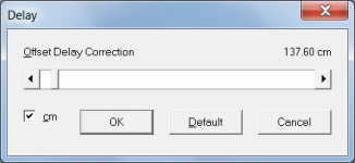
TEST 1. Rather than use the default delay correction specified by Hornresp, set the slider value to the actual time delay due to the horn length. For example, if the horn axial length is 137.60 cm, set the delay slider to 137.6 / 34400 * 1000 = 4.0 msec.
TEST 2. Simulate a direct radiator system rather than a horn system, in Hornresp.
Kind regards,
David
For example, if the horn axial length is 137.60 cm, set the delay slider to 137.6 / 34400 * 1000 = 4.0 msec.
I forgot to add that you don't actually have to do the calculation - simply tick the 'cm' check box and set the slider to the required axial length (see attachment).
Attachments
Are you asking how to make a horn out of one 125x250 pc multiplex (plywood birch)?Sorry if it sound silly,
let say I have 4pcs 18 inch and I like to made a horn use a multiplex let say with 120 X 240cm.
know my question is :
1. how to start use hornresp to made the horn ?
2. Any idea what important thing in woofer data for a horn use ?
3. must I use bracing inside horn ?
When using a 18" you are hardly getting a "real horn" out of this much wood with enough deep bass. "single sheet th 15" challenge" thread deals with how to get one cabinet out of one sheet of wood and suceedes with a 15" and not too much deep bass with a tapped horn.
A "real" horn with a 18" out of one sheet of wood? hm.....
You could go for a bandpasshorn (cervin Wega etc.. style).
Any more information you can provide will help in giving a good answer to your problem.
Bagby's extracted phase is top right, compared to Phase window bottom graph. It's a vague resemblance but it's closer than the SPL + Phase in the top left.
I don't know exactly what Bagby does, but I assume he uses the Hilbert transform, which gives you the minimum phase response given the magnitude response. Then you will get the minimum phase part of the phase response, but not the excess phase part. As long as the system is not minimum phase (and I don't think a horn system is), you will not get the same results from the phase extraction as from Hornresp's calculated phase.
Correct, the Hilbert Bode FFT Transform Minimum Phase Extraction tool is visible in one of the last pictures I posted. (I thought all speakers and all aspects of speakers were minimum phase.)
Anyway, I was just trying to find a correlation between the softwares (a common reference point) so I can be really sure I'm doing everything correctly. I'm used to adding offset manually as a measured distance.
I'll figure it all out but I haven't had 5 minutes to sit down and look it all over yet. I'm going to play around with Response Modeler and Hornresp with more regular alignments and find the correlations to make sure I know exactly what I'm looking at with the phase.
Correct, the Hilbert Bode FFT Transform Minimum Phase Extraction tool is visible in one of the last pictures I posted. (I thought all speakers and all aspects of speakers were minimum phase.)
Unfortunately, they are not. Minimum phase implies that the frequency response is "invertible and stable", in other words, you can equalize it flat and at the same time correct the phase response. You can't do that with all aspects of speakers. Comb filter effects, for instance, is one example, diffraction is another. I can't state this categorically, but in most cases where you combine two versions of a signal (like direct sound and reflection), the resulting response is not minimum phase. And in a horn you will have the superposition of the wave going out from the driver and the wave reflected from the mouth. There may be minimum phase regions, but not everything will be minimum phase.
This link may be useful:
Minimum Phase
Power Compression Option
I asked before about the possibility of adding this option in, but at the time i don't think it wasn't doable ? Well i've been trying to get my head around AkAbak a bit more & on perusing one of the included PDF manuals, i saw this.
Could you take a look at it please, & see if there is anything similar that HR could make use of etc, in order to allow this feature. As well as including the temperature coefficients of copper, aluminiuim could also be included
I asked before about the possibility of adding this option in, but at the time i don't think it wasn't doable ? Well i've been trying to get my head around AkAbak a bit more
& on perusing one of the included PDF manuals, i saw this.Manual Ak21 Exercises.pdf
Page # 27 Exercises
Analyzing temperature-dependent voice coil resistance
Finally, we will analyze the effect of the voice coil temperature on the curve for the acoustic pressure. Please open the script Ex_22.aks.
Could you take a look at it please, & see if there is anything similar that HR could make use of etc, in order to allow this feature. As well as including the temperature coefficients of copper, aluminiuim could also be included
Unfortunately, they are not. Minimum phase implies that the frequency response is "invertible and stable", in other words, you can equalize it flat and at the same time correct the phase response. You can't do that with all aspects of speakers. Comb filter effects, for instance, is one example, diffraction is another. I can't state this categorically, but in most cases where you combine two versions of a signal (like direct sound and reflection), the resulting response is not minimum phase. And in a horn you will have the superposition of the wave going out from the driver and the wave reflected from the mouth. There may be minimum phase regions, but not everything will be minimum phase.
This link may be useful:
Minimum Phase
I don't know much about minimum phase and I don't have time to study it now. I thought minimum phase was simply cause and effect - if the effect always has a predictable cause it's minimum phase. (But I've only briefly peaked at discussions of minimum phase, I've never really been interested in what it is or why it's useful.)
What I do know is that people use Bagby's tools all the time to sim a driver in a box, add diffraction effects, extract minimum phase, add other drivers and a crossover and measure the result. The result is exactly as expected.
Most of the time these measurements are done on axis @ 1m within a measurement window that helps to reduce the room interaction. If we take the same measurements including the room and all of its furishings, no longer min phase. If we were to listen to the same speaker in free space would remain min phase in the absence of diffraction and possible comb filtering.
I asked before about the possibility of adding this option in, but at the time i don't think it wasn't doable ? Well i've been trying to get my head around AkAbak a bit more
Could you take a look at it please, & see if there is anything similar that HR could make use of etc, in order to allow this feature. As well as including the temperature coefficients of copper, aluminiuim could also be included
Hi Zero D,
To calculate the voice coil resistance, it is necessary to know the temperature of the voice coil. The temperature is dependent upon input power, and the relationship between input power and voice coil temperature is not normally known, because it depends upon the physical design of the driver - e.g. voice coil construction, air gap width, chassis heat sink cooling fins, etc.
If the voice-coil temperature is assumed to be 200 deg C, what is the value of Eg?
Kind regards,
David
@ David McBean
Hi, i don't pretend to understand everything they have done, so i've uploaded the PDF i mentioned, with the formula etc. If for some reason uploading it is verboten ? here's the link to their www Download - Akabak
I hope it will be doable now
Hi, i don't pretend to understand everything they have done, so i've uploaded the PDF i mentioned, with the formula etc. If for some reason uploading it is verboten ? here's the link to their www Download - Akabak
I hope it will be doable now
Attachments
Hi Zero D,
I already had a copy, but thanks anyway.
It has always been doable, it's just that I can't see that it would be of much use.
The AkAbak formula enables power compression to be calculated at a given voice coil temperature. What we really want to know is the power compression at a given input voltage Eg.
All the AkAbak formula does is to calculate the resistance of the voice coil at a given temperature, assuming that the original value of Re is measured at 20 deg C.
What would be more useful, would be the ability to calculate the resistance of the voice coil at a given input voltage (i.e. current through the coil), which unfortunately is not possible for the reasons given in my previous post.
Kind regards,
David
Hi, i don't pretend to understand everything they have done, so i've uploaded the PDF i mentioned, with the formula etc.
I already had a copy, but thanks anyway
.I hope it will be doable now
It has always been doable, it's just that I can't see that it would be of much use
.The AkAbak formula enables power compression to be calculated at a given voice coil temperature. What we really want to know is the power compression at a given input voltage Eg.
All the AkAbak formula does is to calculate the resistance of the voice coil at a given temperature, assuming that the original value of Re is measured at 20 deg C.
What would be more useful, would be the ability to calculate the resistance of the voice coil at a given input voltage (i.e. current through the coil), which unfortunately is not possible for the reasons given in my previous post.
Kind regards,
David
Last edited:
It has always been doable, it's just that I can't see that it would be of much use
The AkAbak formula enables power compression to be calculated at a given voice coil temperature. What we really want to know is the power compression at a given input voltage Eg.
All the AkAbak formula does is to calculate the resistance of the voice coil at a given temperature, assuming that the original value of Re is measured at 20 deg C.
What would be more useful, would be the ability to calculate the resistance of the voice coil at a given input voltage (i.e. current through the coil), which unfortunately is not possible for the reasons given in my previous post.
Kind regards,
David
And what you end up with in most simulations is a calculation on the variation on the change in resistance versus power in on the coil.
That is not something that you can call useful when you consider that the motor design has the largest influence on the cooling potentials that are available.
It becomes a situation where you have a nice looking graph, but that graph has little to do with reality.
So although I would like to see this happen, I can not find a definitive paper that really describes how to calculate it in the first place.
It would require a great deal of knowledge of what is inside the motor before any calculation could be truly useful.
Originally Posted by David McBean
What would be more useful, would be the ability to calculate the resistance of the voice coil at a given input voltage (i.e. current through the coil)
I know how to design and sim a circuit to do that, in several ways. But whether such a circuit could be integrated etc into HR ?
@ mwmkravchenko
I appreciate your comments too
I know how to design and sim a circuit to do that, in several ways.
Hi Zero D,
I'm not sure that I understand - are you saying that you have a method for predicting the resistance of a voice coil Re at a given input voltage Eg?
If Re = 6 ohms when Eg = 0 volts, how would you go about calculating the value of Re when Eg = 100 volts, for example? As far as I can see, you would need to know the temperature of the voice coil when Eg = 100 volts, to be able to do that.
Kind regards,
David
And what you end up with in most simulations is a calculation on the variation on the change in resistance versus power in on the coil.
Hi Mark,
I would be interested in having a look at a program that can do that. Is there a name you can give me so I can investigate further? Thanks.
Kind regards,
David
Are you asking how to make a horn out of one 125x250 pc multiplex (plywood birch)?
When using a 18" you are hardly getting a "real horn" out of this much wood with enough deep bass. "single sheet th 15" challenge" thread deals with how to get one cabinet out of one sheet of wood and suceedes with a 15" and not too much deep bass with a tapped horn.
A "real" horn with a 18" out of one sheet of wood? hm.....
You could go for a bandpasshorn (cervin Wega etc.. style).
Any more information you can provide will help in giving a good answer to your problem.
No not just 1 Sheet but use plywoodbirch with standard dimension 120 X 240cm efficient something like with 240cm width 120cm is good enough to me.
the main problem I do not know where to start with hornresp, I have done some calculation with Tractix calc but not sure it will perform.
@ David McBean
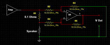
Here's my sim of an I = V converter. R1 samples a portion of the current through the speaker. The U1 output voltage is a scaled representation of the current through the speaker. For eg,
With R1 = 0.1 Ohms & Speaker = 10 Ohms, then 100 Volts RMS in = 1.982 Volts RMS Out. This is double what some might expect via the 0.1/10 ratio, but it's due to the circuit having a gain of two. If required the output could be halved to match the "expected" result.
Scaling R1 and/or Speaker Re up/down will give appropriate results.
If Re was a simulation of a Real speaker, then as I varies so will Re. Therefore the relationship between I/R could be derived by an ohms law calculation.
There is another way to sample I if you're interested.
All the above is just an idea for inclusion, which might not able to be transferable into HR ?
I welcome input from others who wish to help
Attachments
That sim calculation doesn't take into account thermal cooling provided by the real action of a real driver, which will vary depending on the design. The only accurate means I know of without adding additional issues is via non contact. An optical thermopile can achieve this, but then it's an issue of actually seeing the VC in action. This is impossible in most cases without driver modification.
@ David McBeanIf Re was a simulation of a Real speaker, then as I varies so will Re. Therefore the relationship between I/R could be derived by an ohms law calculation.
The problem is that the I/R relationship will be different for every single driver. Sometimes dramatically different. This is what David and Mark have been saying here and it's what several people said the last time this was brought up.
Consider a cheap driver with small gauge voice coil wire and no cooling anywhere in the motor compared to a state of the art pro driver where cooling is a top design goal. How are you going to account for that? A formula can never do that without a bunch of input about the actual driver.
As I mentioned months ago you have options to do this manually. Most people just raise Re (or add Rg) to simulate heat, or you can measure the t/s parameters of your drivers when hot and use those t/s for the sim.
- Home
- Loudspeakers
- Subwoofers
- Hornresp