Isn't the default output the direct output, and output 2 the port output?Weltersys, no the choises are "default", "output 2" and "combined".
No default output is port output.
An externally hosted image should be here but it was not working when we last tested it.
A 280 L closed box with JBL 2226:
From JBL 2226 product sheet:
Has this to do with directivity?
An externally hosted image should be here but it was not working when we last tested it.
From JBL 2226 product sheet:
An externally hosted image should be here but it was not working when we last tested it.
Has this to do with directivity?
My mistake, remembered wrong.No default output is port output.
Hornresp considers the driver as a perfect piston, while real drivers have upper break up that extends upper response past the piston band.
Therefore, the actual measured upper response will usually be higher than simulated.
Last edited:
If it was allowed to start a new section with a new area, four sections would suffice.
Hi Mårten,
Unfortunately almost everything in Hornresp would need to be changed
") .
.Another one for AkAbak?
Kind regards,
David
Has this to do with directivity?
Hi Mårten,
The high frequency extension in the pressure response is due to a combination of directivity effects and diaphragm resonances causing "cone breakup" as described by Art ('weltersys') in Post #4084.
Kind regards,
David
My mistake, remembered wrong.
Hi Art,
I think your memory is probably fine
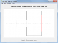
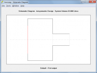
.The default output is determined by how the system is specified in Hornresp.
Attachment 1 - Direct radiator output is the default.
Attachment 2 - Port output is the default.
Kind regards,
David
Attachments
Unfortunately almost everything in Hornresp would need to be changed
I guess a fifth section is out of the question as well.

I guess a fifth section is out of the question as well.
Hi Mårten,
Adding a fifth horn segment to Hornresp is definitely out of the question. I would have to go back to the beginning and completely rewrite the program. Life is too short for that
.Kind regards,
David
Hornresp Update 3340-140120
Hi Everyone,
Having already spent many more hours working on the Filter Wizard than originally planned, despite my best intentions I reluctantly came to the conclusion that adding a few extra hours at this late stage couldn’t possibly make matters any worse. Accordingly, the changes described below have been implemented. The Filter Wizard now has 8563 lines of code equivalent to 143 pages when printed out. So much for my lack of interest in filters...
The logic and code controlling the wizard user interface is now quite complex. I have tested every scenario and condition I can think of, but no doubt I will have overlooked something. Could you please let me know if you find any bugs or notice any inconsistencies in the operation of the wizard - thanks.
CHANGE 1
Filter Wizard settings are retained between calls when the wizard is exited by pressing the Close button. Settings are not retained if the wizard is exited by clicking the 'X' control box or by pressing the Esc key .
CHANGE 2
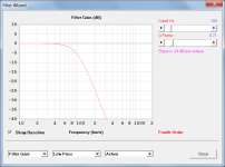
Two additional generalised active filter options have been included. They are called simply 'Second Order' and 'Fourth Order', and enable second and fourth order low pass, high pass and band pass filters to be specified using cutoff frequency and quality factor as inputs (see Attachment 1).
Notes:
When a Q Factor of 0.71 is specified, the Filter Wizard actually uses the more precise value of 1 / (2 ^ 0.5) in the calculations.
A second order filter with Q = 0.50 is equivalent to a second order Linkwitz-Riley filter.
A second order filter with Q = 0.71 is equivalent to a second order Butterworth filter.
A fourth order filter with Q = 0.71 is equivalent to a fourth order Linkwitz-Riley filter.
CHANGE 3
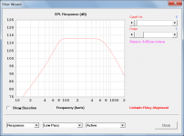
When the Filter Wizard active filter alignment label was double-clicked to switch from First Order Butterworth to Second Order Linkwitz-Riley, the slope label did not change from -6 dB per octave to -12 dB per octave (see Attachment 2). This bug has now been fixed.
Kind regards,
David
Hi Everyone,
Having already spent many more hours working on the Filter Wizard than originally planned, despite my best intentions I reluctantly came to the conclusion that adding a few extra hours at this late stage couldn’t possibly make matters any worse
. Accordingly, the changes described below have been implemented. The Filter Wizard now has 8563 lines of code equivalent to 143 pages when printed out. So much for my lack of interest in filters...The logic and code controlling the wizard user interface is now quite complex. I have tested every scenario and condition I can think of, but no doubt I will have overlooked something. Could you please let me know if you find any bugs or notice any inconsistencies in the operation of the wizard - thanks.
CHANGE 1
Filter Wizard settings are retained between calls when the wizard is exited by pressing the Close button. Settings are not retained if the wizard is exited by clicking the 'X' control box or by pressing the Esc key .
CHANGE 2
Two additional generalised active filter options have been included. They are called simply 'Second Order' and 'Fourth Order', and enable second and fourth order low pass, high pass and band pass filters to be specified using cutoff frequency and quality factor as inputs (see Attachment 1).
Notes:
When a Q Factor of 0.71 is specified, the Filter Wizard actually uses the more precise value of 1 / (2 ^ 0.5) in the calculations.
A second order filter with Q = 0.50 is equivalent to a second order Linkwitz-Riley filter.
A second order filter with Q = 0.71 is equivalent to a second order Butterworth filter.
A fourth order filter with Q = 0.71 is equivalent to a fourth order Linkwitz-Riley filter.
CHANGE 3
When the Filter Wizard active filter alignment label was double-clicked to switch from First Order Butterworth to Second Order Linkwitz-Riley, the slope label did not change from -6 dB per octave to -12 dB per octave (see Attachment 2). This bug has now been fixed.
Kind regards,
David
Attachments
Last edited:
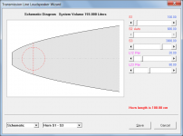
I made a simulation of a TL successfully dampening the first third of the cabinet. However, simulating a MLTL cannot be done since there are not enough sections :-(.
An externally hosted image should be here but it was not working when we last tested it.
Hi Mårten,
Am I correct in assuming that in your design above, ideally you would like to be able to partially fill segment 2 with absorbent material, from S2 to the red line?
Kind regards,
David
You are correct David.
Hi Mårten,
Thanks for the confirmation. Something else for me to think about in my spare time
.Kind regards,
David
Do my eyes see a tab named gain?
Hi Mark,
Sorry, the filters are unity gain only.
The tool is a Filter Wizard, not an Equaliser Wizard
.Kind regards,
David
Something else for me to think about in my spare time
In fact there is. Quite often I do parabolic designs with offset driver. The angle of the first section is the same as the second section. It would be nice to be able to tell Hornresp that two or more sections should have the same expansion rate, and let Hornresp decide the areas between these sections.
David, I'm enquiring about the T factor of the Le Cleach profile.
I've been considering what might be done as far as widening the pattern in the upper octaves with an axissymmetrical horn, either by taking these closer to being conical on their own, or by splicing them near the throat.
Would there be a way I could simulate the properties of a Le Cleach horn with T>1.5? I can obtain the profiles from Jmmlc's spreadsheet.
Quite often I do parabolic designs with offset driver. The angle of the first section is the same as the second section. It would be nice to be able to tell Hornresp that two or more sections should have the same expansion rate, and let Hornresp decide the areas between these sections.
Hi Mårten,
Double-click on the red 'S2 Manual' slider label. In 'S2 Auto' mode the flare rates of segments 1 and 2 become the same, and the value of L12 can be changed without altering the overall flare rate or length.
There is no need to specify more than two segments in an offset driver design if the segments are to have the same expansion rate.
Kind regards,
David
Attachments
Would there be a way I could simulate the properties of a Le Cleach horn with T>1.5?
Hi AllenB,
T for Le Cléac’h horns was limited to a maximum value of 1.5 because of concerns I had regarding the accuracy of the throat acoustical impedance predictions when larger values were used. The Hornresp model has been refined since then, so it may no longer be a problem. I will conduct some tests to see if the restriction can be lifted.
Jean-Michel himself saw little value in using the Le Cléac’h profile above about T = 2 ^ 0.5 or 1.41, which is why I settled on an upper limit of 1.5.
Kind regards,
David
The tool is a Filter Wizard, not an Equaliser Wizard
I should be much more careful with my wishes.
Filter wizard it is.
Is the Q directly addressable? ( Don't know if that is a wurd )
Or linked to the explanation of 2nd and 4rth orders?
- Home
- Loudspeakers
- Subwoofers
- Hornresp