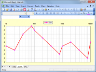
I tried to do it in Excel, and it was very inconvenient and time consuming, and no easy way to build frequency in a logarithmic scale.
Hi Yauhen,
I had in mind something like the attached zipped-up Excel spreadsheet.
Process:
1. Export all Hornresp chart data to csv file.
2. Open exported csv file in Excel.
3. Open attached Gain.xls file in Excel.
4. Copy data from column D in exported csv file to column B in Gain.xls.
The above process should take a matter of seconds.
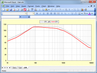
Columns Gain 1 to Gain 5 in the Gain.xls spreadsheet store the different gain profiles you may have. Simply copy the one you wish to use into the relevant column H cells
To keep things simple, linear interpolation has been used to derive the gain values at intermediate points between the 14 sample frequencies.
Kind regards,
David
Attachments
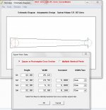
When exporting from the schematic diagram (when one wants to draw their horn out and start folding), my "width" column is represented as width/2. is there a way to stop this? does it have to do with the type of flare I'm using?
Hi sine143,
The change was made from full-width to half-width values some time ago. It is not related to the type of flare you are using. Normally horn profiles are drawn by working from the centre line axis, which makes it convenient to have half-width values specified. Simply multiply each value by 2 if you require the full width.
Kind regards,
David
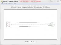
Was well and properly confused wen my 620 liter offset driver horn looked like it was going to fit in a 22.5x22.5x45 inch box lol
") .
.Hi David
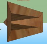
I did try to export for a inverted tapped horn but i get again strange outcomes, can you look at it? thanks. Inverted horns have nice graphs with speakers who do not so well in tapped horns.
I have tryed all possibillities con, uni, par, exp, par go oke for a part until the end is suddenly has errors, maybe a inverted horn kan not be exported.
regards
kees
Attachments
Last edited:
I did try to export for a inverted tapped horn but i get again strange outcomes, can you look at it?
Hi Kees,
As far as I can see, the results are being calculated correctly.
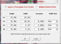
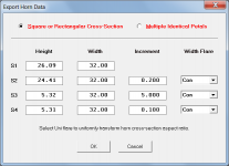
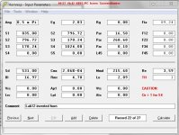
If we consider the first horn segment in your screenprint example:
S1 = 835.00
S2 = 781.22
Specified height at S1 = 32.00
Calculated width at S1 = 835.00 / 32.00 = 26.09 (Hornresp rounds to 2 decimal places)
Specified height at S2 = 32.00
Calculated width at S2 = 781.22 / 32.00 = 24.41 (Hornresp rounds to 2 decimal places)
Because the specified width flare = Con, the width of the first horn segment will decrease linearly with horn length from a half-width at S1 of 26.09 / 2 = 13.045 to a half-width at S2 of 24.41 / 2 = 12.205.
The height value at any point along the horn segment is found by dividing the cross-sectional area at that point by the width.
Calculated half-height at S1 = (835 / (2 * 13.045)) / 2 = 16.002300 (Hornresp rounds to 6 decimal places)
Calculated half-height at S2 = (781.22 / (2 * 12.205)) / 2 = 16.002048 (Hornresp rounds to 6 decimal places)
Note that in this case, height values will not be constant along the length of the horn segment because of the way that Hornresp calculates the results.
To maintain a constant 32 cm dimension along the length of the horn segment, set the width rather than the height to 32 cm, and specify either a Con or Exp width flare (but not a Uni flare) as shown in the attached screenprint.
Kind regards,
David
Attachments
Hi Kees,
The linked post is also relevant.
http://www.diyaudio.com/forums/subwoofers/119854-hornresp-356.html#post3535881
Kind regards,
David
The linked post is also relevant.
http://www.diyaudio.com/forums/subwoofers/119854-hornresp-356.html#post3535881
Kind regards,
David
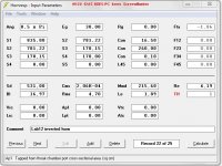
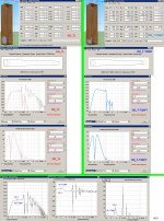
Hi David.
I did see when I do export some more times it has little different outcomes, but it is when I look just a very small 0,1 mm differents it looks however strange.
I do use round numbers, and so this is the result from hornresp. (see picture) a subwoofer 18 to 90 hz ready to sawdust.
I get really experienced with horn folds, I made this fold in just 40 minutes.
Attachments
Last edited:
Hi David
I did try to export for a inverted tapped horn but i get again strange outcomes, can you look at it? thanks. Inverted horns have nice graphs with speakers who do not so well in tapped horns.
I have tryed all possibillities con, uni, par, exp, par go oke for a part until the end is suddenly has errors, maybe a inverted horn kan not be exported.
regards
kees
Kees,
In Post# 3705: The TS parameters for the Lab12 driver is not correct ?
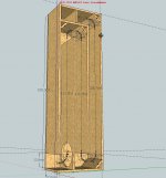
'Inverted horns have nice graphs with speakers who do not so well in tapped horns.'
That's your belief of what you have depicted but definitely not I can imagine. you provided a SketchUp picture that IMO depicts a Quarter-wave OD_TL.IMO to make a good inverted Horn Sub normally takes an IB Driver (Vas very large) like the Altec 416-8B :
See the sample picture:
--------------------------------------
Inverted Horn:
Inverted Horn Loudspeaker
Voigt horn:
'...The entire pipe can be seen as a tapered transmission line in inverted form...'
Voigt pipe - Wikipedia, the free encyclopedia
http://www.greatplainsaudio.com/vintage_altec/416-8B_LF_Speaker.pdf
Improve the knowledge of 'Horn' and Quarter-Wave theories:
Horn theory:
Horn Theory
https://www.grc.com/acoustics/an-introduction-to-horn-theory.pdf
http://p10hifi.net/planet10/TLS/downloads/Dinsdale-Horns-3parts.pdf
b
Attachments
Last edited:
Bjorno
Sometimes I be on the internet and see all kind of exotic enclosures for woofers, afcourse I do not now all, and so I test them, the tapped horn can also be seen as a pipe, a real horn
it is not, but it is coupled as al the others are, a real TL is only a pipe, not coupled to te front of the speaker, I did like that idea of make a transformed to air a smatch, like the real horn does, but size matters when go low, I do like the sound of qarter wave enclosures a TL can sound very good, this technics are so very old also, and still populair.
The old post is not active anymore, the tapped horn will come later, I think i go to horns as a speaker system, but first some tryouts, the open baffle and dipoles I have done, sounds well only I miss the punch a little, and she go not very loud if use as sub.
Now the T-TQWT do play, it do well, one sub for two open baffles, go very low with the two isobaric visatons, who have by the way a very large vas, that is why i did use the isobaric to make a smaller box. see the measurement of the T-TQWT with two open baffles who do the upper bass from 100 hz. next photo is the visaton T-TQWT who is in room for some months now..
But we are on the wrong place, it is offtopic on this place.
regards
kees
Attachments
Last edited:
Hornresp Update 3240-130927
Hi Everyone,
I noticed in the exported horn data listings recently provided by Kees that when a horn segment had only one element, the 'Top Len' values were shown as zero.
The Hornresp code has now been changed so that a horn segment always has at least two elements, and the correct 'Top Len' values are shown.
My thanks to Kees for providing the test data that enabled me to identify this issue.
Kind regards,
David
Kees,
In Post# 3705: The TS parameters for the Lab12 driver is not correct ?
Bjorno
I did see you have change TS parameters, mine in post 3705 are right, Lab 12 is the first tapped horn tryout with a infinity woofer so name is still lab12, but is not the lab 12 speaker.
I have the sim done with the infinty reference 1260W woofer for the inverted horn.
http://ch.infinitysystems.com/tl_fi.../Reference/Reference/1260w/REF1260W_PI_EN.pdf
In photo the TS are oke, there was some errors in previous post.
And now back on on topic, hornresp bugs.
David.
You are welcome, I have done a good thing without notice it myself?.
regards
kees
Attachments
Last edited:
David
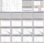
Still, now is changed a other thing, horn section three, when it is there 0,1 then hornresp go only 0,099 and give a long column of tekst, the older version just do well and give a column of two, this give more clarity.
regards kees
Still, now is changed a other thing, horn section three, when it is there 0,1 then hornresp go only 0,099 and give a long column of tekst, the older version just do well and give a column of two, this give more clarity.
regards kees
Attachments
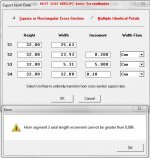
Still, now is changed a other thing, horn section three, when it is there 0,1 then hornresp go only 0,099 and give a long column of tekst, the older version just do well and give a column of two, this give more clarity.
Hi Kees,
The change is intentional. With the old version, the "column of two" meant that the horn segment had only one element and the 'Top Len' values were shown as zero, which is the problem I wanted to fix.
With the new version a segment length of 0,1 has a default increment of 0,001 which gives a 100 elements. Simply change the increment setting to 0,05 or greater to reduce the horn segment to 2 elements, or a "column of three". The maximum allowable increment value is 0,099 to ensure that there are always at least two elements.
Allowing an increment value of 0,1 when the horn segment length is also 0,1 would mean that there was only one element, and that the 'Top Len' values would again be shown as zero.
(In Hornresp at least two elements are required to calculate the 'Top Len' value).
Kind regards,
David
I do use 0,099 then it give 3 rows.
Hi Kees,
I couldn’t resist making a further refinement
.An increment of 0,1 can again be used in your example to give just 2 rows, but with the 'Top Len' (and 'Side Len' for Uni width flare) values no longer being shown as zero.
(Hornresp actually uses two 0,05 length elements internally to calculate the length of the curved 'Top Len' line, but these calculations are not seen by the user).
Kind regards,
David
Hi David
Yes i did now david that you do go look again like a real scientist do.
Very nice and thanks for looking at it, the last row is used in my case as a big hole in a tapped horn two rows is more clear.
Ooh yes i did simulate a synergy horn, can hornresp also simulate the upper range like with a tweeter to 20 khz? a synergy horn has very different aproach because normally I can do use a horn of small size who hornresp do nicely. synergy has also a mid and a bas-mid in the same horn, and so tweeter sim is not accurate, maybe akabak is better for synergy horns, but it is sure interesting also for hornresp, to make things more easy without a script..
thanks and succes with your wonderfull software.
kees
Last edited:
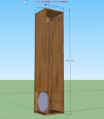
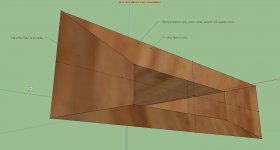
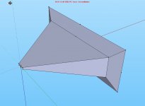
Hi David
Did try the synergy horn with the output of hornresp, only the last flare I gets to wide when it is not a square horn, I did for example 1 x 4 cm start it will then go to 100 cm horizontally and 50 cm vertically, the last flare has to be follow the rest except see difference on photo,s, my english is not as good to go to technical.
I did see with sketchup it is not easy to do the angles right, push pull do only a straight pull up. nice software but maybe I need to learn a more professional drawn program.
regards
kees
Attachments
Hi Kees,
Provided that the driver parameter values and the chamber and horn dimensions used in the simulation accurately reflect those of the actual physical loudspeaker, then I can see no reason why the Hornresp predicted results should not be reasonable. The difficulty of course, is in obtaining accurate drive unit parameter specifications - for high-frequency compression drivers in particular.
If the Synergy loudspeaker configuration is accurately specified in AkAbak, then I would expect the predictions to be more accurate than those possible with Hornresp. I understand that some users have tried simulating a Synergy loudspeaker in Hornresp by manually combining the power response results from two separate horn configurations. The output from a conventional conical horn with the high-frequency driver at the apex is added to the output from the same conical horn but with offset multiple mid-range drivers. Because phasing differences are not taken into account, I am not sure how well the combined theoretical results compare to actual measured performance.
And thanks to you also, for the interest you have shown in Hornresp, particularly with regard to the schematic diagram exported horn information. As a direct result of your feedback, several significant improvements have been made to the generation of this data.
Kind regards,
David
can hornresp also simulate the upper range like with a tweeter to 20 khz?
Provided that the driver parameter values and the chamber and horn dimensions used in the simulation accurately reflect those of the actual physical loudspeaker, then I can see no reason why the Hornresp predicted results should not be reasonable. The difficulty of course, is in obtaining accurate drive unit parameter specifications - for high-frequency compression drivers in particular.
synergy has also a mid and a bas-mid in the same horn, and so tweeter sim is not accurate, maybe akabak is better for synergy horns,
If the Synergy loudspeaker configuration is accurately specified in AkAbak, then I would expect the predictions to be more accurate than those possible with Hornresp. I understand that some users have tried simulating a Synergy loudspeaker in Hornresp by manually combining the power response results from two separate horn configurations. The output from a conventional conical horn with the high-frequency driver at the apex is added to the output from the same conical horn but with offset multiple mid-range drivers. Because phasing differences are not taken into account, I am not sure how well the combined theoretical results compare to actual measured performance.
thanks and succes with your wonderfull software.
And thanks to you also, for the interest you have shown in Hornresp, particularly with regard to the schematic diagram exported horn information. As a direct result of your feedback, several significant improvements have been made to the generation of this data.
Kind regards,
David
- Home
- Loudspeakers
- Subwoofers
- Hornresp