In summary, "close enough for rock'n'roll".
There was never any doubt about that. Can you show the math you are using to approximate the PAR flare with CON segments?
Hornresp Update 3000-121005
Hi Everyone,
CHANGE 1
Three new File menu commands have been added, accessible from the Input Parameters window.
File > New...
Creates a new data file.
File > Open...
Opens an existing data file.
File > Editor...
Moves or copies records from one data file to another, or deletes records from a data file.
The new File menu commands mean that Hornresp records can now be stored across different data files if so desired. The new functionality has been extensively tested but there is always the possibility that I may have missed something. As a precaution it is recommended that a backup copy of any existing Hornresp.dat file be taken and safely archived prior to using the latest release.
CHANGE 2
A chart showing electrical impedance phase has been added, as requested by sebDIY. The chart is generated by selecting the Tools > Phase menu command from the Electrical Impedance window.
As always, could you please report any bugs.
Kind regards,
David
Kolbreck,
Sorry to interupt,but do you have details of your latest horn that replaced Azura 425. Did not see build info on your page. Sorry for OT.
I have been planning for a long time to put up some info. So please be patient, it will come
")
-Bjørn
Suggestion: The throat adapter is in effect a 5th segment. It is always conical, but that should be a minor issue. If it was possible to specify that the throat adapter should be the first segment in an otherwise offset horn, we would gain back that first segment for use in the main part of the horn.
-Bjørn
Hi Bjørn,
Nice try, but I suspect that you probably already know the answer - "Sorry, it's not going to happen."
.It would only be a matter of time before someone then asked for the same technique to be applied to tapped horns. Things would start to get complicated very quickly...
Kind regards,
David
There was never any doubt about that. Can you show the math you are using to approximate the PAR flare with CON segments?
Hi just a guy,
As an alternative to working through the calculations yourself, simply to export the Hornresp schematic diagram horn data for a parabolic segment, and then note the cross-sectional area values at the end points chosen for each of the conical segments used to approximate the parabolic profile.
Hope this makes sense - I'm not sure how else to describe the process
.Kind regards,
David
Last edited:
Hi just a guy,
As an alternative to working through the calculations yourself, simply to export the Hornresp schematic diagram horn data for a parabolic segment, and then note the cross-sectional area values at the end points chosen for each of the conical segments used to approximate the parabolic profile.
Hope this makes sense - I'm not sure how else to describe the process
Kind regards,
David
You described it just fine, that's actually the only way I know how to do it.
I was hoping Don would have a simple equation that would be even faster and easier than doing it that way. The math probably isn't faster or easier but I'm having fun with the thought until someone smashes it with reality.
I was hoping Don would have a simple equation that would be even faster and easier than doing it that way.
Hi just a guy,
I am not sure how Don does it, but the mathematical method I would most probably use is as follows.
Assuming that you have a single parabolic segment defined by S1par, S2par and L12par, and that you want to approximate it by four conical segments.
Define:
X = L12par / ((S2par / S1par) – 1)
X1 = 0
X2 = X1 + 1 * L12par / 15
X3 = X2 + 2 * L12par / 15
X4 = X3 + 4 * L12par / 15
X5 = X4 + 8 * L12par / 15
Then for the four conical horn segments:
S1con = S1par * (1 + X1 / X)
S2con = S1par * (1 + X2 / X)
S3con = S1par * (1 + X3 / X)
S4con = S1par * (1 + X4 / X)
S5con = S1par * (1 + X5 / X)
L12con = X2 - X1
L23con = X3 - X2
L34con = X4 - X3
L45con = X5 - X4
For example:
S1par = 100
S2par = 4000
L12par = 150
Giving:
X1 = 0
X2 = 10
X3 = 30
X4 = 70
X5 = 150
S1con = 100
S2con = 360
S3con = 880
S4con = 1920
S5con = 4000
L12con = 10
L23con = 20
L34con = 40
L45con = 80
I would be interested if anyone has a simpler method.
Kind regards,
David
Thank you David, it's perfect !A chart showing electrical impedance phase has been added, as requested by sebDIY. The chart is generated by selecting the Tools > Phase menu command from the Electrical Impedance window.
Hi just a guy,
I am not sure how Don does it, but the mathematical method I would most probably use is as follows...
Thanks! I'm gonna take awhile to think about all this before asking if you can incorporate that right into the Export wizard thing. I'm not sure it would be worth your time even if it wasn't difficult to implement.
Now can you upgrade Akabak so it can export a text file describing the horn path (csa vs length) like Hornresp does? LOL, just kidding, but that would be nice.
(Seriously though, does anyone know if Akabak can do that? I looked but didn't see that feature.)
I'm gonna take awhile to think about all this before asking if you can incorporate that right into the Export wizard thing.
Hi just a guy,
I can save you some thinking time - the approximation of a parabolic segment using multiple conical segments will not be included in Hornresp
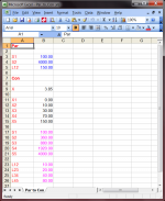
.It is a relatively easy matter though, to set up a simple spreadsheet to calculate the required AkAbak inputs - see attached screenprint.
I can email you a copy of the .xls file if you like.
Kind regards,
David
Attachments
I can email you a copy of the .xls file if you like.
Kind regards,
David
Thanks, that would be great! I hope you didn't make that spreadsheet just for me though. It would make me feel bad to monopolize your time on stuff that doesn't directly involve Hornresp. But still, thanks!
I have some code that appears to work by similar means to David's spreadsheet.
1: Given Y = A * X squared, we have two pairs of X-Y values so we can find the value of A. Because we are working in areas, X squared = area / pi.
2: Parabolic horn curves have more "bend" near the throat and are "straighter" towards the mouth. A good approximation is to make each segment twice as long as the preceding segment as you proceed from throat to mouth. For a 4 segment horn, the segment lengths will be 1x, 2x, 4x, 8x the first segment length. So divide the horn length (distance from throat to mouth) by 1+2+4+8 = 15. The segment lengths will be 1/15, 2/15, 4/15, and 8/15 of the horn length.
3. Using the formula from before, calculate the area at each of the segment joins.
My script is written in an obscure scripting language (REXX). My plan is to find some free time (ha ha) to convert the script to a spreadsheet so it will be useful to others.
Thanks, that would be great!
Hi just a guy,
It seems that files cannot be attached to emails generated from this forum. Could you please send me a standard email so that I can reply to you with a copy of the Excel file as an attachment. My email address is given on the Hornresp download website - simply click on my name on the site.
Kind regards,
David
The equation for a Parabola is Y = a.X² + C
We have our two Areas: S1 and S2. From these we can calculate Y1 and Y2.
Y1 = SQRT[S1 / PI]
Y2 = SQRT[S2 / PI]
if we assume that the element starts at 0 and ends at L12 then:
X1 = 0
X2 = L12 (Length)
a and c can be calculated from:
a = [Y2 - Y1] / [X2² - X1²]
c = Y1 - aX1²
We can then calculate the area at any point along the segment by
Y = a.X² + C
S = PI.Y²
Hi just a guy,
It seems that files cannot be attached to emails generated from this forum. Could you please send me a standard email so that I can reply to you with a copy of the Excel file as an attachment. My email address is given on the Hornresp download website - simply click on my name on the site.
Kind regards,
David
No problem, thanks.
We can then calculate the area at any point along the segment by...
I realize you were talking about something else but this part I've quoted seems like it might potentially lead to something exciting.
Akabak can't give a detailed list of csa vs length like hornresp can. (If it can I don't know how to do it.) Since Akabak won't do PAR segments, there's no real accurate way for a guy like me (that can barely understand the equations you guys are showing) to lay out an Akabak horn accurately, all you can really do is replace the virtual CON sections with straight boards that create PAR segments in the fold plan. It's been historically proven that this isn't a fatal flaw but it's obviously not the most accurate way.
BUT if you can do what I've quoted, but do it with CON sections instead, I could make a spreadsheet that converts an Akabak script (with it's CON segments) to a detailed list of csa vs length like Hornresp does with it's Export wizard.
(This mess created by Akabak's non PAR attitude is the main reason I was hoping for more Hornresp segments. But if I can find an accurate way to lay out Akabak's CON sections that's almost as good.)
BTW, since this isn't about Hornresp specifically I can start a new thread for this if anyone would prefer that.
Last edited:
No problem, thanks.
Hi just a guy,
You've got mail.
Kind regards,
David
(This mess created by Akabak's non PAR attitude is the main reason I was hoping for more Hornresp segments. But if I can find an accurate way to lay out Akabak's CON sections that's almost as good.)
Hi just a guy,
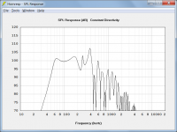
Further to my earlier post about keeping things in perspective, I think you might find in practice that it really doesn't make much of a difference if multiple parabolic segments or multiple conical segments are used in the simulation model. To illustrate, the attached screenprint compares the SPL response of a tapped horn having three conical segments against the response of the same horn, but with three parabolic segments. You can see that the traces are effectively identical. Greater inaccuracies are already inherent in the predictions due to the assumption that the driver diaphragm acts as a rigid plane piston at all frequencies, and that there are no losses due to panel vibrations, etc.
Kind regards,
David
Attachments
- Home
- Loudspeakers
- Subwoofers
- Hornresp