Based on a recent thread of mine ( http://www.diyaudio.com/forums/showthread.php?s=&threadid=108497&perpage=25&pagenumber=1 ), I plan to use 4 Pyle Pro PPA15 woofers ( http://www.partsexpress.com/pe/pshowdetl.cfm?&Partnumber=292-218&CFID=5347580&CFTOKEN=26346424 )to build a pair of double (W profile) ripoles .
Background Theory on Ripoles:
http://www.lautsprechershop.de/hifi/ripol_en.htm
Driver Blurb:
JohnInCR suggested that I extend the rear of the ripole to form a U-baffle extenstion. I plan to do that later via a sliding sleeve.
Excuse me while go puy some plywood")
Background Theory on Ripoles:
http://www.lautsprechershop.de/hifi/ripol_en.htm
Driver Blurb:
Code:
Pyle PPA15
* Power handling: 250 watts RMS/800 watts max * Voice coil diameter: 2-1/2" * Impedance: 8 ohms * Frequency response: 27-4,000 Hz * Magnet weight: 70 oz. * Fs: 26.7 Hz * SPL: 90.2 dB 1W/1m * Vas: 11.36 cu. ft. * Qms: 2.69 * Qes: .89 * Qts: .67 * Xmax: 6 mm * Dimensions: Overall Diameter: 15.06", Cutout Diameter: 13.86", Mounting Depth: 6.02"
JohnInCR suggested that I extend the rear of the ripole to form a U-baffle extenstion. I plan to do that later via a sliding sleeve.
Excuse me while go puy some plywood
Attachments
No, Ripole , .. apparently similar to a dipole except with more restricted front and rear cavities to load the driver better, decreasing Fs, at the expense of some efficiency.
My criteria for sizing the openings are
1. rear cavity cross sectional area approx = 1/3 x driver Sd
2. front common cavity cross sectional area = 2 x rear cavity cross sectional area.
Here are some of my calculations (rounded off where necessary)
All dimensions in inches
magnet diameter 7
driver cutout diameter 13.86
magnet clearance above frame 1.5
nominal mounting depth 5.5
Sd (estimate) 124
internal width 15 (approx)
rear slot height 2.755555556 , .. approx 3"
front slot height 2 x 3 = 6
Hi,
If You post the data in MKS-values I could do a precise simulation for You.
Anyway on first glance I´d rather use a smaller front opening and larger back chambers.
The TS-parameters look ok so far, apart from Fs and Qts.
Fs is quite low for such a dipole. Expect the Fb to be ~10Hz lower!
Qts is a bit high for a 15" driver. Experience showed that a Qts above 0.5 is ok with smaller drivers, but with drivers >12" Qts-values around 0.4 and even smaller simply sound more precise, tighter and cleaner.
If the driver is usable will show when it is built in and working, but from the datasheet it is ok so far.
jauu
Calvin
Calvin said:1) Anyway on first glance I´d rather use a smaller front opening and larger back chambers.
2) The TS-parameters look ok so far, apart from Fs and Qts.
3) Fs is quite low for such a dipole. Expect the Fb to be ~10Hz lower!
4) Qts is a bit high for a 15" driver.
5) Experience showed that a Qts above 0.5 is ok with smaller drivers, but with drivers >12" Qts-values around 0.4 and even smaller simply sound more precise, tighter and cleaner.
6) If the driver is usable will show when it is built in and working, but from the datasheet it is ok so far.
jauu
Calvin
1) The front and rear chambers I believe are supposed to match the surface area of the driver used for proper loading for Ripole use.
2) Actually, the PPA15's T/S parameters are near perfect for dipole/ripole use.
3) You WANT the Fs to be low or you will need loads of EQ and power and Xmax to compensate for the low end.
4) Again, for dipole/ripole use, the PPA15's Qts is just about perfect.
5) For a driver operating in a sealed or ported enclosure, this is true. However, for dipole use, these drivers are the most precise, tightest and cleanest I have ever heard. IOW, the PPA15's motor/suspension system has plenty of control over the cone's movement in OB designs.
6) The PPA15 is VERY usable, no doubt about it. Datasheets are worthless and inaccurate when trying to determind the sound of a loudspeaker or subwoofer.
Calvin said:Hi,
If You post the data in MKS-values I could do a precise simulation for You.
Anyway on first glance I´d rather use a smaller front opening and larger back chambers.
The TS-parameters look ok so far, apart from Fs and Qts.
Fs is quite low for such a dipole. Expect the Fb to be ~10Hz lower!
Qts is a bit high for a 15" driver. Experience showed that a Qts above 0.5 is ok with smaller drivers, but with drivers >12" Qts-values around 0.4 and even smaller simply sound more precise, tighter and cleaner.
If the driver is usable will show when it is built in and working, but from the datasheet it is ok so far.
jauu
Calvin
Whsat data do you want in MKS system, .. the TS parameters or my ripole dimensions, so far? I'm thinking the TS parameters. Here they are:
Code:
Pyle PPA15
* Power handling: 250 watts RMS/800 watts max
* Voice coil diameter: 63.5mm
* Impedance: 8 ohms
* Frequency response: 27-4,000 Hz
* Magnet weight: 70 oz.
* Fs: 26.7 Hz
* SPL: 90.2 dB 1W/1m
* Vas: 0.321679377 cu meters
* Qms: 2.69
* Qes: .89
* Qts: .67
* Xmax: 6 mm
* Sd (approximate value for a 15" woofer with pleated surround) : 0.0856 m2
* Dimensions:
Overall Diameter: 0.382524 meters
Cutout Diameter: 0.352044 meters
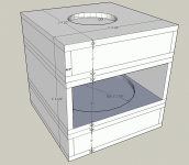
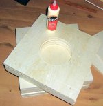
Mounting Depth: 0.152908 metersI've adjusted my dimensions slightly, since the plywood in the store is 48" wide, . not 49" like I had expected it to be. I'l have be rebate away a little wood to allow the driver to fit
Attachments
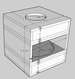
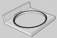
This is what I'll have to do to make sure the driver frame fits . Ths top part won't be glued in, but will be held in place by threaded rod .
Calvin, I'll wait on your simulations and build the baffles in the mean time. I thought I followed the rule of thumb correctly ie.
1. opening cross sectional area (rear) = 1/3 x Sd
2. double the front cross sectional area to account for the fact that I'm using 2 drivers per ripole (facing each other).
What am I not accounting for?
Attachments
chops said:
5) For a driver operating in a sealed or ported enclosure, this is true. However, for dipole use, these drivers are the most precise, tightest and cleanest I have ever heard. IOW, the PPA15's motor/suspension system has plenty of control over the cone's movement in OB designs.
6) The PPA15 is VERY usable, no doubt about it. Datasheets are worthless and inaccurate when trying to determind the sound of a loudspeaker or subwoofer.
Chops, I think what Calvin means is that the ripole construction loads the driver more than a conventional open baffle design and accordingly, the motor has to be able to cope.
We'll find out soon enough. For starters, I'm not going to glue in any of the "spacers" that determine rear or front chamber height, so if the ripole doesn't work out, I'll just make spacers taller to morph the ripole into a conventional w-profile dipole design.
Calvin, if you need, here are the current dimensions in mm
Here's
Attachments
zobsky said:
Chops, I think what Calvin means is that the ripole construction loads the driver more than a conventional open baffle design and accordingly, the motor has to be able to cope.
Agreed, but still nowhere near as much as coping with the forces within a traditional sealed or vented enclosure.
I have one of these PPA15 drivers in a sealed 4.2cf enclosure for center channel duties, and it does a pretty decent job, considering...
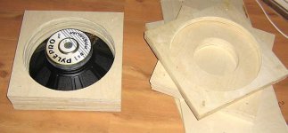
Nothing exciting yet, .. merely cut the panels to size and routed out the magnet pass-through holes. If you can keep the dimensions of the panels to just a little under 16", you should be able to build a pair of cabinets out of one 4 x 8 " sheet of plywood.
Attachments
I dont want to hijack the thread, but is there any hard data on Ripole construction and calculations? I see numbers like "25% of Sd" and "lowers Fs by 15%" but is there any math that predicts this?
A few have quoted the MJK design worksheets as well as the dipole calculations, but only casually.
Other than experimentally, is there any way to "design for Ripole"?
Thanks!
Matt
A few have quoted the MJK design worksheets as well as the dipole calculations, but only casually.
Other than experimentally, is there any way to "design for Ripole"?
Thanks!
Matt
y8s said:... is there any hard data on Ripole construction and calculations? I see numbers like "25% of Sd" and "lowers Fs by 15%" but is there any math that predicts this?
AFAIK: A model for the Ripole configuration has been developed with
Akabak. This model is not published. So for a accurate calculation of a ripole you need someone with access to that model. The numbers you have mentioned have been published as ballpark numbers by people with access to that model.
Hi,
don´t write ´perfect parameters for Ripole´ when Calvin says: "OK but not perfect"
If You´d plan a Linkwitz-type dipole or OB I´d agree with Chops, even if I´d still prefer a somewhat lower Qt (remember that a Qtb between 0.5 and 0.7 is recommended as best ). With Ripoles its a slightly different matter.
The original Ripole lowers the Fs typically between 10Hz and 15Hz.
Just building a dipole compartment doesn´t mean building a Ripole!
A Ripole always comes with a passive EQ, that lowers the Fb further!
So 27Hz together with very small chambers will probabely result in a subsonic Fb (~12-15Hz) which is not useful at all.
It´s the script Rudolph talks of that is in usage by A.Ridtahler and someone else and the sim-results and actual measurements are quite consistent.
@Zobsky:
I need the dimensions of Your suggested dipole compartement.
jauu
Calvin
don´t write ´perfect parameters for Ripole´ when Calvin says: "OK but not perfect"
If You´d plan a Linkwitz-type dipole or OB I´d agree with Chops, even if I´d still prefer a somewhat lower Qt (remember that a Qtb between 0.5 and 0.7 is recommended as best ). With Ripoles its a slightly different matter.
The original Ripole lowers the Fs typically between 10Hz and 15Hz.
Just building a dipole compartment doesn´t mean building a Ripole!
A Ripole always comes with a passive EQ, that lowers the Fb further!
So 27Hz together with very small chambers will probabely result in a subsonic Fb (~12-15Hz) which is not useful at all.
It´s the script Rudolph talks of that is in usage by A.Ridtahler and someone else
and the sim-results and actual measurements are quite consistent.@Zobsky:
I need the dimensions of Your suggested dipole compartement.
jauu
Calvin
Calvin said:Hi,
don´t write ´perfect parameters for Ripole´ when Calvin says: "OK but not perfect"
If You´d plan a Linkwitz-type dipole or OB I´d agree with Chops, even if I´d still prefer a somewhat lower Qt (remember that a Qtb between 0.5 and 0.7 is recommended as best ). With Ripoles its a slightly different matter.
The original Ripole lowers the Fs typically between 10Hz and 15Hz.
Just building a dipole compartment doesn´t mean building a Ripole!
A Ripole always comes with a passive EQ, that lowers the Fb further!
So 27Hz together with very small chambers will probabely result in a subsonic Fb (~12-15Hz) which is not useful at all.
It´s the script Rudolph talks of that is in usage by A.Ridtahler and someone else
@Zobsky:
I need the dimensions of Your suggested dipole compartement.
jauu
Calvin
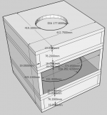
After cutting the square wood pieces down, trimming them to size etc
The realistic central compartment interior dimensions = 368 mm (W) x 387 mm (L)x 152 mm (H)
The 2 rear compartments dimensions = 368 mm (W) x 387 mm (L))x 76 mm (H)
I haven't cut the pieces of wood that make up the height of the individual compartments (the H pieces) so let me know what you think are optimal sizes (and why). For my initial estimates, I used Srear = 1/3 x Sd and Sfront = 2 x Srear (dual ripole)
From your post, I think that excessive driver loading will be unnecessary for these drivers since their Fs is low to begin with.
Thanks
Essentially, all anyone with Akabak would need to do is model an acoustic compliance on either side of the driver, followed by an acoustic resistance (defined by the size of the slot).
Any word on how a Ripole would work with only the rear or the front of the driver resistively loaded?
Any word on how a Ripole would work with only the rear or the front of the driver resistively loaded?
Calvin said:Hi,
don´t write ´perfect parameters for Ripole´ when Calvin says: "OK but not perfect"
If You´d plan a Linkwitz-type dipole or OB I´d agree with Chops, even if I´d still prefer a somewhat lower Qt (remember that a Qtb between 0.5 and 0.7 is recommended as best ). With Ripoles its a slightly different matter.
The original Ripole lowers the Fs typically between 10Hz and 15Hz.
Just building a dipole compartment doesn´t mean building a Ripole!
A Ripole always comes with a passive EQ, that lowers the Fb further!
So 27Hz together with very small chambers will probabely result in a subsonic Fb (~12-15Hz) which is not useful at all.
It´s the script Rudolph talks of that is in usage by A.Ridtahler and someone else
@Zobsky:
I need the dimensions of Your suggested dipole compartement.
jauu
Calvin
Well I have to admit, since for some reason I find it very difficult to find any information on the Ripole concept and design on the net, I don't know a whole lot about them. Such as ripoles lowering the Fs... I know that they do, but I didn't know by how much.
You stated that ripoles can lower the Fs by as much as 10-15Hz. If that's the case (and I'm quite surprised that it's that much), then yeah, I'd say the PPA15's Fs might be too low. How would that differ from a driver with say a 40Hz Fs? That would get you down to 25-30Hz, but how would the overall bass output sound and perform compared to the PPA15's 12-17Hz Fs?
I've always thought that the lower the Fs is, the better, and that the driver would perform better throughout the bass range until it reached below its Fs in any style enclosure. Is this not the case?
I'm guessing that if I were looking to build a really good ripole with good bass extension, I would look for a driver with an Fs of about 35Hz, so that would get me down to 20-25Hz mounted to the ripole?
Also, how different are the Qts requirements for ripoles compared to dipoles? Does the Qts also shift in one direction when used in a ripole that we should be aware of?
And are there any good sites that really get into the guts of ripole designs and concepts?
In any case, I rigged together one last night with the side pieces pressure fit via threaded rod . I'll try and get some impedance measurements later tonight so we can see what's going on.
Subjectively, this thing is INEFFICIENT Agreed, all I have for now is a 100 W power amp (Mcintosh 2100)driving it fed off the LFE of my reciever, but I've had to max it out and at that point, it's subjectively just about able to keep up with the efficient arrays. The pure dipole seemed to work with the gain turned up around half as high. I haven't rigged up the 2nd ripole yet, .. those drivers are in the MDF board for now.
The bass is subjectively clean (though I think) the pure dipole bass has better attack . The ripole doesn't pressurize the room and is subjectively even ie. no annoying peaks, it's clean. Good for music. Individual notes on the bass / synth are well defined. Cone motion is evident but seems somewhat less than the flat dipole. SPL measurements seem fairly flat down to Fs taken at the mouth, ... but drop off in the 30s when taken at listening position. .
Big disappointment for home theater effects. Explosions are wimpy sounding. I was expecting a bit more in the "sock you in the chest" department. I'm guessing that this isn't what ripoles are designed for, though. It could also be that the motor isn't strong enough for a ripole, as suggested earlier in this thread.
Dimensions are similar to my sketchup models posted earlier in this thread. Maybe I should change those dimensions. Any suggestions?
The neat thing about the way things are set up right now is that I can easily change this to a linkwitz type W-baffle or a ripole of different dimenstions by cutting up new spacers (side pieces). I'm wondering if I should decrease the ripole loading.
Hi,
@Zobsky
based on Your data the simu for 2 drivers (electricaly paralleled) says:
fb(wo.filter): 16.9Hz
Fb(w. filter): 16Hz
so we have indeed ~10Hz lower resonance than freeair!
upper resonance: 270Hz (~+15dB) ||| with filter: none
f-3dB with filter: 180Hz
Zmin: 2.7ohms @100Hz
Zmax: 11.7ohms on fb
suggested filter:
Lser: 3.9mH 0.4 plus minus 0.1ohms
Lpar: 1mH, 0.25ohms
Cpar: 320µF
excursions:
@20Hz, 7V, 5mm
@30Hz, 17V, 5mm
@40Hz, 32V, 5mm
@Chops
Your assumptions are quite right.
A large 15" or 18" driver with a Fs around 30-35Hz could reach down to ~20Hz in a small ripole.
From my experience it always showed that such drivers (You find a few of them with good parameters) can be found at professional manufacturers (PA). These drivers show regularly a better behaviour when asked to handle large amounts of power than those with a lower fs (because of a softer suspension), especially when the supsension is made stiffer (for higher Fs) and with progression.
The Qt rises a bit in ripole, but not much.
jauu
Calvin
- Status
- This old topic is closed. If you want to reopen this topic, contact a moderator using the "Report Post" button.
- Home
- Loudspeakers
- Subwoofers
- My Ripole Project