There is a balanced bridge application called Servo-Sound active speaker.
US Patent 3647969 - Tadeusz Korn Servo-Sound active speaker
Unfortunately, his patent is unclear about how to connect the transistor-based circuit represented as FIG. 5 inside the patent.
Tadeusz did it on purpose, I guess.
If you are lucky enough to find such Servo-Sound active speaker, you may try reverse-engineer it.
Unfortunately, all components involved into FIG.5 are potted with resin.
Some time ago somebody told me one can dissolve some potted resins using acetone or possibly tetrachlorure, I don't remember precisely.
Watch out for toxicity. Read first about acetone and tetrachlorure !
One way to mitigate the voice coil heating problem is to use the Dynaudio type drivers which have a massive voice coil and hence surface area to give better cooling. The Hi-Vi, Dynavox and Morel copies of the Dynaudio are available but now relatively expensive. I do not think you can buy Dynaudio drivers anymore but the complete speakers are relatively cheap, so might be a source.
The purpose of sensing the output current (depending of course of the back-EMF of the driver) in Stahl's method is to achieve a power amplifier with a special complex output impedance such as the whole electrical system, amp+driver is deeply modified from the usual configuration of pure voltage drive.
Albeit probably not very realistic, an open-loop amp having a negative impedance and additional features as required in Stahl's method is conceivable,
the concept would nevertheless remain entirely valid.
Stahl has made it very clear in his JAES article :
"ACE Bass Is not a Feeback System."
*
Concerning the thermal behavior of the voice coil, its effect seems to be largely overestimated for loudspeakers in domestic conditions. Most people having experience with Voigt's bridge feedback and the like have found unnecessary to compensate it.
However, Yamaha deals with the problem, and Ian Hegglun proposed a nice DIY solution in "Speaker Feedback", Wireless World, May 1996, p380.
*
There is an overlooked problem with the techniques using driver current sensing : the inductive nature of the voice-coil which is constant neither with frequency nor in the voice-coil position in the gap.
It is an annoying factor which somewhat limits the achievable potential, no more 10-12 dB of correction has been mentioned in the case of Voigt's bridge.
The purpose of sensing the output current (depending of course of the back-EMF of the driver) in Stahl's method is to achieve a power amplifier with a special complex output impedance such as the whole electrical system, amp+driver is deeply modified from the usual configuration of pure voltage drive.
Not sure what your point is above...
Albeit probably not very realistic, an open-loop amp having a negative impedance and additional features as required in Stahl's method is conceivable,
the concept would nevertheless remain entirely valid.
Stahl has made it very clear in his JAES article :
"ACE Bass Is not a Feeback System."
That should read "ACE Bass Is not a Motional Feeback System."
ACE-BASS most definitely uses feedback around the driver!
Concerning the thermal behavior of the voice coil, its effect seems to be largely overestimated for loudspeakers in domestic conditions. Most people having experience with Voigt's bridge feedback and the like have found unnecessary to compensate it.
I have seen studies (not of ACE-BASS systems) that showed that voice coil heating in a loudspeaker was not significant. The driver, however, were not undergoing the massive power boost that typical ACE-BASS systems apply, and so will not undergo the same level of VC heating. You realize that ACE-BASS does boost power to extend and flatten the response, don't you? You can easily see this if you model the circuit using Basta!. The requirements for power are often quite high.
Actually there was a study, referenced earlier in this thread I think, that showed that the frequency response of ACE-BASS can vary from -2dB to +10dB with voice coil heating. Also, the "benefits" of the circuit are only obtained when Re is very closely cancelled by the negative output impedance of the amplifier.
However, Yamaha deals with the problem, and Ian Hegglun proposed a nice DIY solution in "Speaker Feedback", Wireless World, May 1996, p380.
*
There is an overlooked problem with the techniques using driver current sensing : the inductive nature of the voice-coil which is constant neither with frequency nor in the voice-coil position in the gap.
It is an annoying factor which somewhat limits the achievable potential, no more 10-12 dB of correction has been mentioned in the case of Voigt's bridge.
I am very interested in getting a copy of Hegglun's article. If you or anyone has one that would be willing to share, please contact me.
Can somebody explain how you can have feedback including the speaker and not consider it motional feedback?
As far at Stahl's remark is concerned, people will say the darndest things to qualify for a patent. As I (and more importantly on this topic, Elliot) said before, long history of exactly that.
With montional feedback, there is more power pumped into the VC at those very rare times when there is a music signal that low (say, below 25 Hz). But at resonances, I would guess a MF amp cuts the power in order to cut the motion. For very short moments of overshoot, I'd guess the MF amp does provide strong power to the driver in order to counter-act the over-shoot.
To assess whether heating is a big issue or not, you need to know the distribution of peaks in actual music reproduction, not test with continuous tones in a lab.
Ben
help for calibration
I intend to build a pair of speakers with the ace bass system. seeing the patterns of post # 11 and # 20, I can't figure out how to calibrate the P4 and Pot "a" pots from 100k, if someone would tell me the procedure I thank them.
I would also like to use an Ljm L7 as an amp, is it possible?
I intend to build a pair of speakers with the ace bass system. seeing the patterns of post # 11 and # 20, I can't figure out how to calibrate the P4 and Pot "a" pots from 100k, if someone would tell me the procedure I thank them.
I would also like to use an Ljm L7 as an amp, is it possible?
Hi!!
If you have any questions to the original inventor (K-E S) you can post them here - he's my neighbour
//
I'm already in possession of a pair of a4-14mk2 and sub b2-50, they sound good to me.
I would like to build a similar pair for my brother, using inexpensive speakers on the market (Polish STX type).
Joe has more to say here:
Joe Rasmussen "Trans-Amp" - 40 Watt Transconductance "Current Amplifier"
Joe Rasmussen "Trans-Amp" - 40 Watt Transconductance "Current Amplifier"
Thanks all for your help so far.
I tried to do some simulations with WinISD for both sealed and reflex cabinet.
Parameters of Focal speaker without ACE:
Sd : 0,0165 m2
fs : 40,4 Hz
Vas : 37,2 l
Qts 0,294
Mmd : 0,0161 kg
Bl : 6,05 N/A
Rdc: 3 Ohm
Cms*: 0,0009639 m/N (*calculated)
Qes* : 0,34
Qms* : 2,404
Rms* = 1,7 kg/s
Simulated parameters for sealed enclosure of 20l with Qtc = 0,5 :
fs : 11,76 Hz
Mmd : 190 g
Rms : 35,55
Qes : 1,151
Qms : 0,395
This gives a -3db point of 30 Hz. The only thing that worries me is that WinISD gives a SPL of less than 70db. Can this be true, or is it different in real life because the added mass to the cone is only virtual.
I also tried to simulate a bassreflex enclosure . The problem is that enclosures smaller than 20l needs port length of several meters! to get a low fs (30Hz or lower). The only way to get a normal length is to increase Vas, but thats not what you want! Simulated parameters:
fs : 19,6 Hz
Mmd : 68,4 g
Rms : 16.45
Qes : 0.690
Qms : 0,512
How can I determine the Qts and Vas for the desired results?
I hope that someone here can give me some help with the design process.
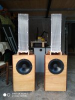
Sorry, link is brokenHere are a few pictures:
Read more on my blog, and download schematic and calculation sheet:
AceBass up and running | Baldin's Blog
I made a small PCB for the circuit, but it is easily made up on a bit of breadboard.
I would love to hear if someone fries it out .....
Best regards Baldin
Hi all.
where I can look AceBass up and running | Baldin's Blog the link is broken.
where I can look AceBass up and running | Baldin's Blog the link is broken.
Sorry merovingio, this page was not maintained after going to Wordpress!
What do you need?
Attached is the calculation xls file, and the schematics used.
I haven't played with ACEBASS for quite some time, and do not have a system currently running.
I don´t have the original web files, so this is the best I can do, without having to re-invent the whole thing")
Hope it helps.
One caution I found, is using acebass with self oscillating class d amps, as you'll be placing an additional loop around the amp. This will cause the switching frequency to increase. The remedy is to adjust the switching freq back down again for the amp itself
What do you need?
Attached is the calculation xls file, and the schematics used.
I haven't played with ACEBASS for quite some time, and do not have a system currently running.
I don´t have the original web files, so this is the best I can do, without having to re-invent the whole thing
Hope it helps.
One caution I found, is using acebass with self oscillating class d amps, as you'll be placing an additional loop around the amp. This will cause the switching frequency to increase. The remedy is to adjust the switching freq back down again for the amp itself
Attachments
Because we stupidly use woofers with primary resonance within the passband*, and for other reasons including changes in the weather, motional feedback is just not a rock-steady loop. So with Class-D amps and all other amps, keep a close eye on things during development*. And hard to sell MFB commercially, esp in Australia where the sinks empty in the opposite rotation swirl.***One caution I found, is using acebass with self oscillating class d amps, as you'll be placing an additional loop around the amp. This will cause the switching frequency to increase. The remedy is to adjust the switching freq back down again for the amp itself
B.
* of course, that's a big reason for needing MFB
** and use a woofer that can handle 500 watts if you amp poops out at 200 watts
***caution, California law requires notice that this post may contain elements of attempted humour
Thanks I serarch this!!!Sorry merovingio, this page was not maintained after going to Wordpress!
What do you need?
Attached is the calculation xls file, and the schematics used.
I haven't played with ACEBASS for quite some time, and do not have a system currently running.
I don´t have the original web files, so this is the best I can do, without having to re-invent the whole thing
Hope it helps.
One caution I found, is using acebass with self oscillating class d amps, as you'll be placing an additional loop around the amp. This will cause the switching frequency to increase. The remedy is to adjust the switching freq back down again for the amp itself
My secret dream is to make a hybrid speaker with a cell that works from 200hz up and an ACEbass that goes from 200hz down.
After years of testing I made the cell, which works well (actually I built the machines to build the cell first) using the cells of my Acousta Monitor4 as a reference.
Obviously I like Baldin's idea better than building an ACEBass amp because it allows me to use standard amps.
However, I have seen that Stahl puts some calibration trimmers that are not in the ACEBassPreamp. I sincerely thank Baldin and all those who replied to me, I continue to develop.
Attachments
- Home
- Loudspeakers
- Subwoofers
- ACE-bass amplifier design