I've built a Pass F5T and I'd like to wire up the two XLR female connectors incase I decide to use them in the future.
From what I've read about XLR, there's a bit of voodoo that takes place somewhere along the line (the difference of two wires get's thrown out) perhaps at the connectors?
I want to be sure I get the wiring correct for them, and didn't find much about wiring up the actual connectors vs new wires on youtube and the web.
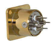
I got a pair of Cardas CM F XLR
CM F XLR (Female XLR)
From the internal boards, I have a Left +, Left - and Right +, Right -.
thanks
From what I've read about XLR, there's a bit of voodoo that takes place somewhere along the line (the difference of two wires get's thrown out) perhaps at the connectors?
I want to be sure I get the wiring correct for them, and didn't find much about wiring up the actual connectors vs new wires on youtube and the web.
I got a pair of Cardas CM F XLR
CM F XLR (Female XLR)
From the internal boards, I have a Left +, Left - and Right +, Right -.
thanks
Attachments

Your + goes to pin 2, - to pin 3, signal ground (same as RCA ground) would go to pin 1. The fourth pin is for chassis ground in the event that signal ground and chassis ground are different. Many times they are the same. This will help you with the pinout: XLR Pinout - Drawings & Colours - 3 pin & 5 pin XLR connectors
Neil Muncy actually traveled around to manufacturers (some pretty big names) to explain the proper way of wiring XLRs. Many of them did have the 'Pin 1' problem in their gear. It is worthwhile to verify how the XLR of an old piece of gear is wired and if the problem is there, to rewire it as recommended by the standard nowadays.
well standards nowadays aren't much better and there's still too many misconceptions about grounding in general and many of those are easy to find if you have an internet connection.
Neil Muncy's work to undo the problem of the practice of attaching a chassis ground to a circuit ground is still largely misunderstood.
Neil Muncy's work to undo the problem of the practice of attaching a chassis ground to a circuit ground is still largely misunderstood.
- Home
- More Vendors...
- Sonic Craft
- wiring for chassis XLR