the original problem was when tryied to operate boras amp legend 4 with voltage 60-66vdc per rail ......
it all end up to almost 150 very expensive mosfets send to outer space while testing and trying to make it work ......
input was to sensitive to anything like a hot suap of plugs or just a litle bit of overdrive
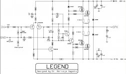
bora of course recomended to add 0.18R 5W to the out of every mosfet as first change
and then a 33-56 pf miller styroflex capacitor between b and c on the MJE 340 vas amplifier to improove some ocilation was there
schematic is also available ......
still didnt work
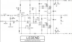
destroyer x a very nice guy from brasil his original name is Carlos Eugênio Mergulhão - Destroyer x and me worked out some mods and in real life this all seems to work no matter if used or abused ha ha ha ....
the new schematic is also available
it all end up to almost 150 very expensive mosfets send to outer space while testing and trying to make it work ......
input was to sensitive to anything like a hot suap of plugs or just a litle bit of overdrive
bora of course recomended to add 0.18R 5W to the out of every mosfet as first change
and then a 33-56 pf miller styroflex capacitor between b and c on the MJE 340 vas amplifier to improove some ocilation was there
schematic is also available ......
still didnt work
destroyer x a very nice guy from brasil his original name is Carlos Eugênio Mergulhão - Destroyer x and me worked out some mods and in real life this all seems to work no matter if used or abused ha ha ha ....
the new schematic is also available
Attachments

Bora is an electronic teacher....he is not too much young...he is an electronic
Enginneer teacher.....he is one of those that "create engineers"
It is possible that others had copied him too.
But also, it is not difficult that two folks create almost the same idea in different places...as all of us have brain inside skull.... even knowing that some folks has skull only to support hairs
There are things that makes some pressure on designers...now a days, i think, a digital amplifier may be something that will born everywhere in many different designs...and some of them will be almost the same without copies or spyes working on it.... sounds nice (not perfect) but it is small, low consumption and can be made inside small chips.
Also we are a result of our environment, this new world were communications are fast and easy..with internet informing almost all you need...those technologic evolutionary methods of amplifier design are beeing published around the world...and everybody has some influence on that...as not one appeared in this earth finishing some travel that started in Mars.... we go reading and learning other folks ideas, and this may result in something new...but not entirelly new, having influences of many designers.
regards,
Carlos
nice schematic
very nice schematic victor ....i presume is very powerfull also
but please can you tell us where is the relation with the legend 4 we are talking about .... (?????? )
also simulation looks prety nice also but this project ever made real life ?????? and how was it ????
can we see may be pictures of it ????
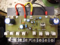
irfp 250 attachment to board
well this wasnt easy thing to do ...... i had to first solder all fets to board plan to fit them with 3mm metric allen screw but then in the heatsink was drills with 4mm diameter ....so any soldering mistake was covered by the tolerance of the hole .....
could also use a gamma corner to attach fets into hetasink but didnt want to use the efficiency of that particular hetasink cause is made from better quality alouminioum than the corner i had ....
nice though ...produces about 240w and its very very stable ...... bench tests all come out very good but real life .....will see after easter ...i have some small show to produce and planing to use that ....just for fun !!!!!
irf atach....
well the truth is that i first soldered all irf in the board very very carefully and i used 3mm metric allen screws but in 4mm hole ...so lets say if a made soldering mistakes of 0.5 mm this could be covered by the tollerance of the hole ....
not very practical and it was done on existing heatsink didnt want to attach an alouminioum corner on it cause of size but also cooling effectivity .....
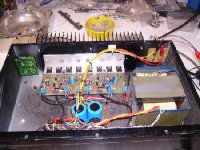
real life legend 4
there is a picture of real life legend 4 stereo constructed in a inter m 2300 old existing
this is capable of almost 165 w rms @8R with 66+66 vdc psu also tested in real life in a party actually pushed to the limit for more than 5 hours ...working as second way in bi amp system (2way high )
all went just fine
Another spy discovered that Sakis is handsome...look alike a Hollywood artist
I have many spies.... i am able do discover a lot of secrets.
hehe...we are never alone when we have friends.
Congratulations Sakis....you look alike a Greek statue.
regards,
Carlos
I have many spies.... i am able do discover a lot of secrets.
hehe...we are never alone when we have friends.
Congratulations Sakis....you look alike a Greek statue.
regards,
Carlos
Attachments

- Status
- This old topic is closed. If you want to reopen this topic, contact a moderator using the "Report Post" button.
- Home
- Amplifiers
- Solid State
- Boras Legend 4 Mosfet Amp