tinitus said:
I have two supplies - a small with 58Vdc and a big with 52Vdc
Wonder if input and driver stage can used with 58Vdc
Nah, looks close - but I guess I could just use another driver fore the MJL/21193/21194 I have already
Could that be done without changes
Dual Supply, for input/driver and Output
is a very good thing.
Maybe not as obvious, when people do only simulations
with one ideal virtual supply (voltage source).
But in real life ... is very
 different.
Real transformers and supply is Not Ideal.
There is a lot of talk about PSRR - Power Supply Rejection Ratio.
This talk comes a lot from the bad use of only 1 supply in power amplifiers.
What is stopping people from using a smaller trafo for pre-stages?
Could not be money.
Because the trafo need is often very small.
Regards, lineup
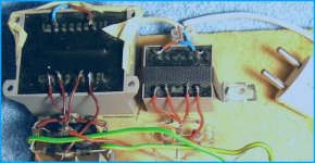
Attachment:
One typical Lineup Audio Lab amplifier supply.
Two Transformers!!
Like Mr John Curl does
")
Attachments

Re: Here is another image.
My avatar ..... hmmmm
It was taken today, in my little photo-studio
in a little free space, in my only room I Have to live in.
I have bought 2 special photo lamps, so need no flash light and get natural colours.
It is really not an avatar
But as you do not follow my postings and my TOPICS
how would you know It Is A 1024x768 WALLPAPER!!!!!!
It is all properly described, The Story of this wallpaper
in my new thread:
diyAudio Wallpapers 1024x768 Your Creation!
Regards
lineup - The Best Photographer!
destroyer X said:BTW...Lineup...beautifull avatar..congratulations
regards, Carlos
My avatar ..... hmmmm
It was taken today, in my little photo-studio
in a little free space, in my only room I Have to live in.
I have bought 2 special photo lamps, so need no flash light and get natural colours.
It is really not an avatar
But as you do not follow my postings and my TOPICS
how would you know It Is A 1024x768 WALLPAPER!!!!!!
It is all properly described, The Story of this wallpaper
in my new thread:
diyAudio Wallpapers 1024x768 Your Creation!
Regards
lineup - The Best Photographer!
destroyer X said:This image is a clown in my culture...hummm..very offensive, but as you do not know....i will forget and will point my cannons to other place.
It's not a clown but a joker or jester, not quite the same as a clown. Jester's have that funny hat, but in a deck of cards he is called a joker. Jesters were very important characters in royal courts of days gone by.
Oh...this is much better...Joker...all rigth.
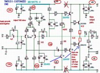
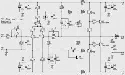
Tinitus...here is the schematic.
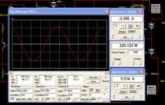
Attention please friends...this is some simulator result...an i do not believe entirelly in simulations...i do not trust, as i had some problems.
But it may work fine, after real life adjustments.
It is NOT guaranteed...do it under your own risks and blame the damn simulator if something goes wrong...needing adjustment.
This is not the Dx Standard amplifier..also this is not Dx turbo...also it is not the Ignitor amplifier made to Sparkle.
This is Tinitus X amplifier..customized made to answer his questions.
Your output may be very good Tinitus...despite there are people that say they have too big capacitance...aaagh!...people say a lot of things...grumpf...hard to know everything..we have to test what they say all time long...never trust...try by yourself!]
Please, do not forget to join the supply grounds....i do not think you are an idiot...this is because I am an idiot and i use to forget those things.
You may need to use at least 3 output pair when 4 ohms speakers will be used.....to 8 ohms you can face the risk with a single pair (Oh! my God!...boooom!)
Each output must have emitter resistor...and each one must have 4,7 series resistor into the base (stoppers....and with those transistors that people say that...say this...say those...much better not to forget to stop resistors)
There are parts that will need replacement...for instance...all condenser will need 64 volts units...or more insulation voltage.
The transistors will be the ones that will hold bigger supply voltage.
Note the increase of the Miller capacitor...in the simulator i perceive unstabilities during 80 Kilohertz reproduction...virtual reproduction.... you will not be listening...but maybe some Bats around...or other animals....good audio for them too!
You will see painted red the resistances moved.... carefull, 220 watts can melt a lot of speaker dear Tinitus...i hope you are experienced and very old with those explosions.
Attention ALL...ONCE again...this is not guaranteed, this is not the standard Dx amplifier...this is special, made only to friend Tinitus.
regards,
Carlos
Tinitus...here is the schematic.
Attention please friends...this is some simulator result...an i do not believe entirelly in simulations...i do not trust, as i had some problems.
But it may work fine, after real life adjustments.
It is NOT guaranteed...do it under your own risks and blame the damn simulator if something goes wrong...needing adjustment.
This is not the Dx Standard amplifier..also this is not Dx turbo...also it is not the Ignitor amplifier made to Sparkle.
This is Tinitus X amplifier..customized made to answer his questions.
Your output may be very good Tinitus...despite there are people that say they have too big capacitance...aaagh!...people say a lot of things...grumpf...hard to know everything..we have to test what they say all time long...never trust...try by yourself!]
Please, do not forget to join the supply grounds....i do not think you are an idiot...this is because I am an idiot and i use to forget those things.
You may need to use at least 3 output pair when 4 ohms speakers will be used.....to 8 ohms you can face the risk with a single pair (Oh! my God!...boooom!)
Each output must have emitter resistor...and each one must have 4,7 series resistor into the base (stoppers....and with those transistors that people say that...say this...say those...much better not to forget to stop resistors)
There are parts that will need replacement...for instance...all condenser will need 64 volts units...or more insulation voltage.
The transistors will be the ones that will hold bigger supply voltage.
Note the increase of the Miller capacitor...in the simulator i perceive unstabilities during 80 Kilohertz reproduction...virtual reproduction.... you will not be listening...but maybe some Bats around...or other animals....good audio for them too!
You will see painted red the resistances moved.... carefull, 220 watts can melt a lot of speaker dear Tinitus...i hope you are experienced and very old with those explosions.
Attention ALL...ONCE again...this is not guaranteed, this is not the standard Dx amplifier...this is special, made only to friend Tinitus.
regards,
Carlos
Attachments
Tinitus.... if you construct....be happy with it
It may disturb neighboors....it may kick all rats out of your house ...may crack some walls...and burn some speakers.
Your supply will need to be fat of electrons...good one....400 watts to each channel to allow small loss of voltage during consumption peaks.
Use, at least, 20000 uf to each rail when using two channels.
hehe...enjoy.
Carlos
Attachments
Oh!..it is raining cats and dogs here...the temperature is wonderfull now.
You will be green of envy guys....hehe...22 degrées celsius...lovely temperature.
Brazil is a lovely country...and twice in a year we have good temperature...ahahahhaa
regards,
Carlos
You will be green of envy guys....hehe...22 degrées celsius...lovely temperature.
Brazil is a lovely country...and twice in a year we have good temperature...ahahahhaa
regards,
Carlos
Attachments

Hey Sparkle...you are the guilty!...or the responsable for our movement.
Mr. Greg Erskine made what you suggest...or at least, what you may be thinking.
I now you love Aksa as i do...but this is a shame copy...hehe.
he can use copyrigth against us...maybe during our happy meetings..with lovely Hugh Dean
Well hugh...we can use some:
"under license of....."
Maybe will work.... oh pain!...this is really small imagination!...all we could do is to go NEAR related what hugh use to do..he is really the Master of the Universe.
here is Greg work...fine...really fine...sorry Greg to put you inside that trouble.
regards,
Carlos
Attachments
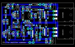
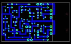
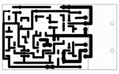
Re: The black and white negative image to produce boards.
106.68 mm x 60.96 mm
destroyer X said:
Hey Greg!...can you inform, please, the board dimensions....as they have increased in length
regards,
Carlos
106.68 mm x 60.96 mm
Nice looking layout but it could be smaller and shouldnt LR be placed NOT in the middle of things? also LR is way too small i think(physically)..
I'm sure it sounds ok, It's a basic design and i have nice experiences with bd139/40 transistors, they are ok..
Why don't you have ccs on input..
Did you think of making a similar amp but with complementary (and symmetrical) path. I like the results the simulator say about 3rd and above harmonic .. compared to my old simple amps..
I've got low noise levels already with the simple one, how are your's? I guess it wont be higher with complementary symmetrical blabla design where there is 2 or 4paths that joins instead of just one, the simulator says that noise levels is way better on my newer ones, again irl i dont know..
I've got a few designs also but of which two I use every day.
The really simple one I made a few years ago..
http://hem.bredband.net/nikwal/evo1.gif Looks almost like that schematic not exacly..
But still sounds ok and hav'nt gone up in smoke..
Below are not finished designs (think of them as ideas)..
http://hem.bredband.net/nikwal1/kifs-comp.gif
works good as hell in the simulator but IRL i dunno(multisim is good but not perfect at all so)..
http://hem.bredband.net/nikwal1/kifsboa.gif
Made a layout too..
Re: dx amp
That's a good suggestion, but I think Carlos may already be very aware of that one. I have an idea that he may have deliberately left that one out.
regards
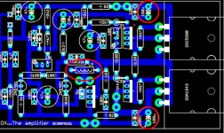
p robertson said:hi carlos,i like your dx amp but may i suggest a possible improvement by putting a non polar cap across R19 say 0.1uf to speed up switching of output stage. hpoe you have room on pcb!
That's a good suggestion, but I think Carlos may already be very aware of that one.
I have an idea that he may have deliberately left that one out.regards
i am sure he did left that one out with a reason...
the layout looks perfect to me - now we can connect this to some heatsink that is horizontal or vertical - no problem....
Hugh Dean is not owner of that idea of having capacitors in front of the output transistors - in fact if i remeber he did not put them there at all on his boards....those cap's on his boards are completely to the left (very near to the input of the amplifier) so............ also - this is only normal thinking - if you have something that is on your way - you try to make things differently in order not to have that on your way any more...
GREG - beautifull work - congratulations for your work and for not getting mad because of me.....
nikwal said:
Why don't you have ccs on input..
Dear nikwal,
ccs in the input produces a certain type of sound that not everyone likes....not having ccs in the input is why Aksa 55 has (in my point of view) simply unbeatable treble....that is what Carlos wanted here - not to copy Aksa - that is for sure (since Aksa 55 look a little bit diferently when we are talking about input) - but to have unbeatable treble ....this design is common in a lot of amps....good and reliable
it seems to me that he also suceeded to have very, very good bass and midles too.....
it seems to me that this amplifier is unity of very nice and simple design that is not to much simple to destroy the good sound and that in fact sounds great.....
that is why i will make it - but as soon as i catch a little bit of time - since the time is a killing factor in my place.....i simply need 48 hours in 24 hours day......
nikwal said:Nice looking layout but it could be smaller and shouldnt LR be placed NOT in the middle of things? also LR is way too small i think(physically)..
I'm sure it sounds ok, It's a basic design and i have nice experiences with bd139/40 transistors, they are ok..
Why don't you have ccs on input..
Did you think of making a similar amp but with complementary (and symmetrical) path. I like the results the simulator say about 3rd and above harmonic .. compared to my old simple amps..
I've got low noise levels already with the simple one, how are your's? I guess it wont be higher with complementary symmetrical blabla design where there is 2 or 4paths that joins instead of just one, the simulator says that noise levels is way better on my newer ones, again irl i dont know..
I've got a few designs also but of which two I use every day.
The really simple one I made a few years ago..
http://hem.bredband.net/nikwal/evo1.gif Looks almost like that schematic not exacly..
But still sounds ok and hav'nt gone up in smoke..
Below are not finished designs (think of them as ideas)..
http://hem.bredband.net/nikwal1/kifs-comp.gif
works good as hell in the simulator but IRL i dunno(multisim is good but not perfect at all so)..
http://hem.bredband.net/nikwal1/kifsboa.gif
Made a layout too..
I'll thank you for your suggestions before Carlos reads them. If you look back a few pages you will find Carlos is after someone to build his suggested amp not redesign it. He has many years experience in building amps, knows all the tricks and has personal access to many good amp designers.
From your schematics you posted, I would suggest you look at the SKA by Greg Ball. I think you will find his amp is the logical conclusion of what *you* are trying to do.
regards
- Status
- Not open for further replies.
- Home
- Amplifiers
- Solid State
- Destroyer x Amplifier...Dx amp...my amplifier