HI!
Sorry for no pics ... still can't find my camera's charger.
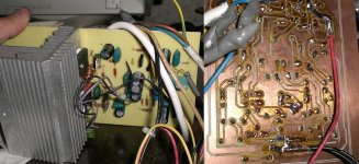
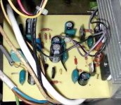
I assembled my first DX!!!!!!!!!!!!!
I am using 25-0-25 power supply for start (+-38 later)
What a great feeling... i turned power on.... NO SMOKE around.
It's a progress for me.
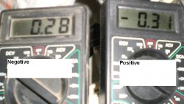
For +-25V supply (with 10ohms 5W resistors) it shows me 310 (positive) and 280 (negative) mV... Is it OK???? In Greg's web there is 1100 and 800mV... but as I am using lower PS I think it's ok!?
Other pics later (just one pic of my dead camera)
regards,
microp
Sorry for no pics ... still can't find my camera's charger.
I assembled my first DX!!!!!!!!!!!!!
I am using 25-0-25 power supply for start (+-38 later)
What a great feeling... i turned power on.... NO SMOKE around.
It's a progress for me.
For +-25V supply (with 10ohms 5W resistors) it shows me 310 (positive) and 280 (negative) mV... Is it OK???? In Greg's web there is 1100 and 800mV... but as I am using lower PS I think it's ok!?
Other pics later (just one pic of my dead camera)
regards,
microp
Attachments
Microp..... from 0.600 to 1100 will be fine.
It is fine...this current will work fine....but.....not absolutelly needed to be so high this way.
Not needed to go to 1100 or up..the equipment will be more hot than the needed temperature.... this value was a "guarantee that will work sugestion of current"...the unit will work fine using lower currents too.
The idea is to mark the potentiometer adjustment and listen the amplifier into very low volume..... than decide the one your amplifier will sound better when volume is very low..... that volume you will need to put your ears touching the speaker.
Or try a headphone for testings.
The 1100 suggestion is a guarantee that the amplifier will not be underbiased...just that....for safety reasons.... your amplifier will sound fine, reading from 600 milivolts (0.6V) to 1100 milivolts (1.1V)..... you decide the better one.
If you do not want to decide.... adjust to 700 milivolts the positive rail and let this way.
When you replace your supply, you will need to readjust.
regards,
Carlos
Thank you all the information Usernames and Charlie-fd
Also the images you sent....i have observed all them.
Thanks by the TNT magazine testings.....Molto Buonno!...grazie!
Also the link with the PDF..... good too.
Graham is my teacher...older and more experienced.... i love when he enter to help,he belongs to the Dx crew..as Greg, Klaas, Nordic and all folks that have some experience and had constructed Dx units.
Now he is trying to tell you that 800 miliamps will be a problem.
Well...you may know that...but...if you wanna try...good luck!
regards,
Carlos
Yes.... was a misunderstanding...good to produce a fine adjustment the way you are
doing...this will make adjustment easier Usernamex and Charlie_fd
I was thinking about that some days ago...but fast i gave up..because a lot of guys will decide different transistors and different supplies, also different selection of bootstrap current..... tweaking the Voltage amplifier current..than...the adjustment splited in such way will be more problem to me than solution.
To avoid complains i will keep the way it is.... but for sure your technical decision was appreciated.
Not so hard to adjust.... i had not problems here with standard trimpots...those old ones.
But i understood...smooth the adjustment...turn it easier..having more room to turn more degrees the trimpot.
I will not include it in Dx amplifier, as this will depends that people will obbey all the schematic parts, voltages and currents...and this do not happens always, as people loves to introduce their own ideas...
To introduce into Dx,amplifier, this better method to adjust bias, i would have to modify schematic, boards and a lot of details....i will keep them the way it is...but i like the idea..very good!
regards,
Carlos
Attachments
You are welcome Microp...now you belong the the crew too
Anything you need...just call me....if i was out or busy, for sure Graham, Klaas, Usernamex, Charlie_fd, Greg, Nordic and other folks will help you for sure.
I am sorry....my memory is not so perfect...i know there are many others..i have to colect all those names and datas...i am having problems with "short time memory"... i am turning old (56).
I have to produce the Dx Crew Map.... with names and places.... i will do it soon.
Needing something, use my mail:
panzertoo@yahoo.com
I can arrange myself to understand Italian, French, Spanish and a little of English too.
You are welcome.
Now you belong to the crew!
Congratulations
Carlos


Hi Carlos,
That was a good misunderstanding.
Not having 800mA is real cool !
Hi usernamex,
>> Ferrite beds on rails supply coming into transformers.
From what I know, it helps reducing EMI/RFI. <<
Okay, now I see what you are thinking; to reduce supply noise.
Actually I think beads between transformer and bridge or even between mains and transformer could increase diode switching EMI.
To minimise rectifier generated noise (and they do generate a high frequency switching buzz) connect one 470nF to 1uF capacitor across each diode in the PSU bridge.
Also use a proper line filter between your mains cable and the transformer primary with its earth connected to the common ground. These enclose grounded L-C filters
I always use a line filter to cut out fridge clicks etc. and other mains switching noises.
Cheers ........ Graham.
Hi Nordic,
The value necessary is probably related to the AV rating of the transformer, the peak current draw, and whether the core is E-I / T-U or toroidal.
I checked this out for myself and would not choose to use less than 470nF on a wide bandwidth AF power amplifier.
I'm sure the source you read stated the merit of suppressing the diode switching transient though.
(Did the tooth come out okay ?)
Cheers ...... Graham.
Ok! Amp is still working beautiful
I would like to know how to calculate output power at 4 and 8 ohms
and how to know power supply suggested power. .....
Sorry for non long answers ... I am so excited I can't write... my brains
are cooked... need few days to rehabilitate.
I would like to know how to calculate output power at 4 and 8 ohms
and how to know power supply suggested power. .....
Sorry for non long answers ... I am so excited I can't write... my brains
are cooked... need few days to rehabilitate.
- Status
- Not open for further replies.
- Home
- Amplifiers
- Solid State
- Destroyer x Amplifier...Dx amp...my amplifier