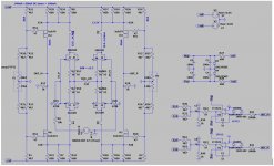
More about the 2S2A2XX power amp,
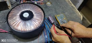
If anyone wants to build the 2S2A2XX power amp shown in previous posts, I can provide all the info needed. This is an amp with excellent accuracy, has more than 110 dB S/N ratio for the 50 W / 8 Ohm version, (60 uV un-weighted, wide bandwidth noise measured on an 8 Ohm load).
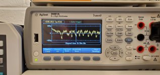
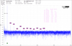
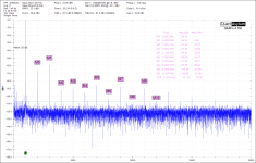
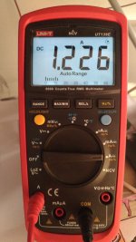
Excellent offset stability, see the attached image showing readings taken for two and a half hours. Very low distortion, see the spectra. The sound is extremely clean, smooth, detailed and very precise.
VG
If anyone wants to build the 2S2A2XX power amp shown in previous posts, I can provide all the info needed. This is an amp with excellent accuracy, has more than 110 dB S/N ratio for the 50 W / 8 Ohm version, (60 uV un-weighted, wide bandwidth noise measured on an 8 Ohm load).
Excellent offset stability, see the attached image showing readings taken for two and a half hours. Very low distortion, see the spectra. The sound is extremely clean, smooth, detailed and very precise.
VG
Attachments
You CAN actually be clean at 84ppm. I don't consider 84ppm as a "unclean" amp.
All that silver and glass , tube amp clipping and harmonics can be had with BJT's.
Low noise ?? this is a sourcing choice.
Hard clip spectra ... this is my latest "fetish". I'm sure someone will party
and overdrive one of my 200W AB amps. I even want that to sound good.
PS - higher power ,4R load ... the H3 increases . I know how to mitigate that.
OS
Last edited:
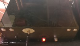
My JLH 10W (22V DC)
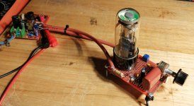
Hi guys, I put a video here, showing a little bit of the audio quality of my JLH.
Test - AMP JLH 1969 (10W) 22V DC - YouTube
Audio is not very good, as it was recorded with the cell phone mic.
I am finalizing the assembly of the amplifier, to make it stereo.
Getting ready I show his amplifier and sound quality recording with a recorder.
Tiago Sierra
Attachments
That JLH looks very nice! I would like to try one out some day.
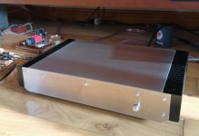
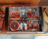
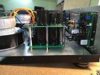
Here is my lockdown amp.
Hand built 2 piece stainless chassis housing self etched Elvee's Circlophone, power management circuit, speaker protection and PS PCB's.
130 watt into 4ohm.
Preamp is built and ready for chassis - it will have a single magic eye as power indicator / signal display.
Working really well with a new set of Wharfedale Evo 4.3's
Attachments
That JLH looks very nice! I would like to try one out some day.
Here is my lockdown amp.
Hand built 2 piece stainless chassis housing self etched Elvee's Circlophone, power management circuit, speaker protection and PS PCB's.
130 watt into 4ohm.
Preamp is built and ready for chassis - it will have a single magic eye as power indicator / signal display.
Working really well with a new set of Wharfedale Evo 4.3's
GREAT!!!!! Good Job!!
GREAT!!!!! Good Job!!
Obrigado!
Brazil is the best place. I met some genius people there...
One ex air force guy in a Sao Paolo favela , he made his own helicopter on his roof. Used recycled parts. Good memories.
Is the JLH sounding good? What kind of signature (if any)?
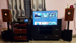
Amplifiers: DIY Jean Hiraga Super 30W Mono Block Class A Amplifiers
Speakers: DIY Alpair 10.3M Full Range Speakers in GR Research Bass Reflex Bookshelf cabinet design
Pre-amp: DIY passive pre-amp and source selector
DAC: SMSL M8 DAC
Source: Raspberry Pi Volumio USB Out or Sony Android TV Optical Out to DAC

Here is a short video of the system : DIY Jean Hiraga Super Class A Amplifier and Alpair 10.3M BS Speakers - YouTube
Speakers: DIY Alpair 10.3M Full Range Speakers in GR Research Bass Reflex Bookshelf cabinet design
Pre-amp: DIY passive pre-amp and source selector
DAC: SMSL M8 DAC
Source: Raspberry Pi Volumio USB Out or Sony Android TV Optical Out to DAC
Here is a short video of the system : DIY Jean Hiraga Super Class A Amplifier and Alpair 10.3M BS Speakers - YouTube
Attachments
Last edited:
Everything about that system is beautiful!!!
Big fan of wood fascias.
Timber for the timbre 8D
Thank you!
")
Member
Joined 2009
Paid Member
Amplifiers: DIY Jean Hiraga Super 30W Mono Block Class A Amplifiers
Speakers: DIY Alpair 10.3M Full Range Speakers in GR Research Bass Reflex Bookshelf cabinet design
very nice set up
Som,
That's a nice setup you have there.
Also like the "blast from the past" in the form of the cassette player and radio combo, aka "Two in One". It still works?
Thanks zmano1!
Radio used work when I checked last - don't want to risk blowing stuff up by powering up to test - I want to restore it completely. It's been in the family for more than 35 years! And I've few hundred cassettes to play too!!
Thank you Bigun!very nice set up
Soothing Guitar on DIY Jean Hiraga Amplifier and Alpair 10.3M Speakers : Vol 4 - YouTube
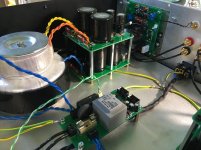
Blowtorch clone
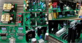
Below are pictures of the third iteration of both circuit as PCB. Now I'm happy.
Before power dissipation was to high.
I lowered rail voltages to +-27V and bias through lateral cascode mosfet's to 51mA. JFet's (BL) are biased to 7mA (=14mA as an alternative for the V version). That's why I've 2 x2SK389BL and x2 2SJ109BL Jfet's instead of 1x 2SK389V and 1x 2SJ109V.
Startup DC-offset is trimmed to a few mV's using trimmer's in resistor devider's for the cascode's. By doing this I was able to lower the time constant of the DC-servo even more.
PSU and regulator: CRCRC quasimodo snubbered + LM317 + shunt regulator (IRF9520) + cap multiplier with 2SK1058 (POS) and 2SJ162 (Neg).
Now I can start with the volume control based on the Muses 72323. Damn these are small bastards (2 have been delivered)
First iteration was here:https://www.diyaudio.com/forums/solid-state/96192-post-solid-pics-709.html#post6611050
Attachments
Class A SE
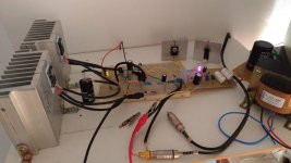
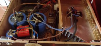
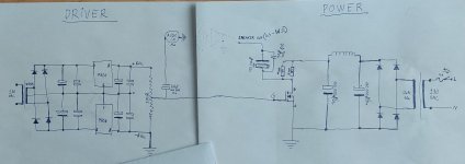
Here is more or less my diy setup for SE pure Class A amplifier.
My toroid transformer can delivery 12vAC 36A, and my rectifier can handle 50A.
And Two 6v soures are actually +6 and -6 linear regulators whit own board separated for main circuit, except biasing voltage and signal feed with ground connection to main board.
Output capasitor to speakers are aluminium 16v and 100 000uF and
Polypropylen 47uF 400v.
I know i have mistake here, and it is input impedance.
For future i change that +6 and -6 get own 200ohm resistor and purpose is make some load for regulators so it keep it stable.
And then i change trimmer something like100-200kOhm and input coubling capasitor maybe something else too.
Now it is 330uF 16v electolytic LowESR type.
My sound source is computer with desent sound card and can handle very well low impedances, so no problem for now on...
Main circuit resistors is two times 1ohm +-10%(parallel 0.5ohm) and can handle with cood cooling to 600w Max eatch.
Transistor is rated more then 500watt.
And i have measured that when input signal is 0.128v rms, output voltage is 1.015v rms, when speaker is connected.(nominal 2ohm load)
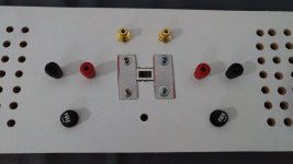
It have own switch front to chose for speaker output Back or headphone output front.
And headphone output is mono just like speaker output so left and right are parallel, and direct connection without any lowering resistors etc...
My headphones are bayerdynamic 990 Pro 250ohm
So parallel it is 125ohm.
B+ is 13.3v(+-0.2) DC
Bias voltage is 4.99vDC
And q point is about 6.6 (+-0.2)
Mains load is about 245watts with fans...
Ripple voltage for speaker output is 3-5mv.RMS
I have a PI filter type setup for smoothing.
Before schoke filter ripple is 90mv.RMS, so i think its filtering very well after that...
PS. Switch and fuse draw backwards...
Here is more or less my diy setup for SE pure Class A amplifier.
My toroid transformer can delivery 12vAC 36A, and my rectifier can handle 50A.
And Two 6v soures are actually +6 and -6 linear regulators whit own board separated for main circuit, except biasing voltage and signal feed with ground connection to main board.
Output capasitor to speakers are aluminium 16v and 100 000uF and
Polypropylen 47uF 400v.
I know i have mistake here, and it is input impedance.
For future i change that +6 and -6 get own 200ohm resistor and purpose is make some load for regulators so it keep it stable.
And then i change trimmer something like100-200kOhm and input coubling capasitor maybe something else too.
Now it is 330uF 16v electolytic LowESR type.
My sound source is computer with desent sound card and can handle very well low impedances, so no problem for now on...
Main circuit resistors is two times 1ohm +-10%(parallel 0.5ohm) and can handle with cood cooling to 600w Max eatch.
Transistor is rated more then 500watt.
And i have measured that when input signal is 0.128v rms, output voltage is 1.015v rms, when speaker is connected.(nominal 2ohm load)
It have own switch front to chose for speaker output Back or headphone output front.
And headphone output is mono just like speaker output so left and right are parallel, and direct connection without any lowering resistors etc...
My headphones are bayerdynamic 990 Pro 250ohm
So parallel it is 125ohm.
B+ is 13.3v(+-0.2) DC
Bias voltage is 4.99vDC
And q point is about 6.6 (+-0.2)
Mains load is about 245watts with fans...
Ripple voltage for speaker output is 3-5mv.RMS
I have a PI filter type setup for smoothing.
Before schoke filter ripple is 90mv.RMS, so i think its filtering very well after that...
PS. Switch and fuse draw backwards...
Attachments
- Home
- Amplifiers
- Solid State
- Post your Solid State pics here