Hi apex,
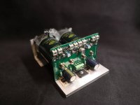
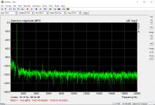
Thanks for your complement. No, there is a servo in the circuit and works quite well, I might add. Initially I took the amp into operation without the servo. For simulation purpose, I also neglected to insert the servo to speed up the simulation since the old software version I have only uses one CPU core. Things take seemingly for ever... Even tho I had all components paired, there was still a nagging offset of about 70mV on the output. Once I installed the servo, it went below what I can measure. My DMM shows 0.0mV however I doubt my Fluke is that precise but I'd say with confidence the offset is less than 1mV.
Your work looks good to. The board material you used looks very familiar to me. Back than my work did not look as clean as yours, I must admit.
I suggest to use SU-V7 or SU-V9 schematic, circuit is similar but dual-fet current is 2mA work better and DC offset is better.
Regards
I suggest to use SU-V7 or SU-V9 schematic, circuit is similar but dual-fet current is 2mA work better and DC offset is better.
Regards
Alright, I have a look at it. I thought the SU series amps were all fully integrated amps.
xrk971
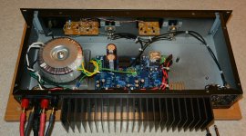
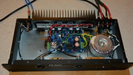
Very nice cooling system for the amplifier.
Some day I must try some A-class myself, never build one so far.
Winter time there is about 5deg C in my office so I would really every aspect of Aclass would be highly recommended.
Mile
The A40 spider looks really cool on the board.
regards
Pit
Very nice cooling system for the amplifier.
Some day I must try some A-class myself, never build one so far.
Winter time there is about 5deg C in my office so I would really every aspect of Aclass would be highly recommended
.Mile
The A40 spider looks really cool on the board.
regards
Pit
Attachments
xrk971
Very nice cooling system for the amplifier.
Some day I must try some A-class myself, never build one so far.
Winter time there is about 5deg C in my office so I would really every aspect of Aclass would be highly recommended
Mile
The A40 spider looks really cool on the board.
regards
Pit
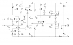
AA14 is simple class A amplifier it can give you idea for your class A amp.
Attachments
Hi Apex,
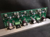
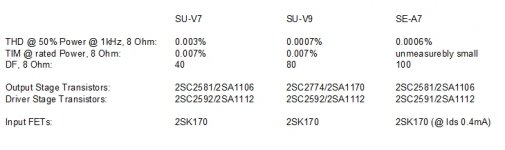
Well, comparing the published specs. this is a bit of a head scratcher. The SE-A7 sports the better specs, yet uses the same OPS and drivers as the SU-V7. I am not sure, using the same components, how the specs in particular the dampening factor can be so vastly different. Either the transistors were much improved over time or the SU-V7 has poor output conductivity or layout deficiencies. Altho the circuits seem very very similar, if not identical, I am puzzled on the specs been so different. Well, I played a bit with the simulation, it appears increasing the current through the input FETs does not seem to help improve the amp performance, it seems to worsen. However, doubling the current through the intermediate stage improved THD significantly, effectively halfing THD figure at 20kHz ! I admit, I am not sure what you mean by better DC offset. How much better than less of a millivolt is this going to get ?
Well, comparing the published specs. this is a bit of a head scratcher. The SE-A7 sports the better specs, yet uses the same OPS and drivers as the SU-V7. I am not sure, using the same components, how the specs in particular the dampening factor can be so vastly different. Either the transistors were much improved over time or the SU-V7 has poor output conductivity or layout deficiencies. Altho the circuits seem very very similar, if not identical, I am puzzled on the specs been so different. Well, I played a bit with the simulation, it appears increasing the current through the input FETs does not seem to help improve the amp performance, it seems to worsen. However, doubling the current through the intermediate stage improved THD significantly, effectively halfing THD figure at 20kHz ! I admit, I am not sure what you mean by better DC offset. How much better than less of a millivolt is this going to get ?
Attachments
Hi Apex,
Well, comparing the published specs. this is a bit of a head scratcher. The SE-A7 sports the better specs, yet uses the same OPS and drivers as the SU-V7. I am not sure, using the same components, how the specs in particular the dampening factor can be so vastly different. Either the transistors were much improved over time or the SU-V7 has poor output conductivity or layout deficiencies. Altho the circuits seem very very similar, if not identical, I am puzzled on the specs been so different. Well, I played a bit with the simulation, it appears increasing the current through the input FETs does not seem to help improve the amp performance, it seems to worsen. However, doubling the current through the intermediate stage improved THD significantly, effectively halfing THD figure at 20kHz ! I admit, I am not sure what you mean by better DC offset. How much better than less of a millivolt is this going to get ?
SU-V7 and SU-V9 have tone control filters in feedback path, use same feedback as SE-A7... DC offset without servo will be better.
AA14 is simple class A amplifier it can give you idea for your class A amp.
That amp will clip with rounded corners and clamp saturations.
Will actually dissipate less when overloaded.
Nice.
OS
That amp will clip with rounded corners and clamp saturations.
Will actually dissipate less when overloaded.
Nice.
OS
Bias 1,2A heatsink around 55deg
YouTube
The making of the SE-A7 Tribute.
Images are in no particular order.
I suggest people try this A7 amp. The sound is amazing
.jpg")
.jpg")
.jpg")
.jpg")
.jpg")
.jpg")
.jpg")
My Amp Camp Amp with toroidal transformer :


more info in my web site:
DIY ACA class A amplifier with linear power supply. - Audiophile Diyer
more info in my web site:
DIY ACA class A amplifier with linear power supply. - Audiophile Diyer
Here are images of my Frankenstein amp. I bought a dead amp for a few bucks on eBay (as opposed to stealing it from grave in the movie) and stuffed it with new DIY board (LJM MX100 on eBay). It's alive!
Attachments
Hi Marra,Secondly a pair of monoblocks based on the brilliant Avondale Audio NCC300 amp boards. These are for myself and I am very much enjoying the sound quality of these amps.
i like it, do you have a closer pic of the transformer? thanks
Hi Hicoco; the transformers are AST fully potted with dual centre tapped secondaries which are connected in parallel for the NCC300's.
These were bought from Les Wolstenholme of Avondale Audio. I have no connection with the company other than as a satisfied customer.
.JPG")
These were bought from Les Wolstenholme of Avondale Audio. I have no connection with the company other than as a satisfied customer.
Last edited:
Thank Marra, what does AST mean for A..... Sound Technology ??Hi Hicoco; the transformers are AST fully potted with dual centre tapped secondaries which are connected in parallel for the NCC300's.
These were bought from Les Wolstenholme of Avondale Audio. I have no connection with the company other than as a satisfied customer.
Here are images of my Frankenstein amp. I bought a dead amp for a few bucks on eBay (as opposed to stealing it from grave in the movie) and stuffed it with new DIY board (LJM MX100 on eBay). It's alive!
Good Idea , I might buy a "parts or repair" EBAY unit for my "greenamp'.
Even a pro amp with fan/tunnel , class H will very rarely need the fan to
run.
Pro amp might even have the dual secondary trafo (for H/L rails).
OS

Thank Marra, what does AST mean for A..... Sound Technology ??
Advanced Sound Technology.
Just tought I'd share some pictures of Fab's new Class AB FSSA-2 amplifier.
It is a CFA amplifier, powered with +/-45Vdc and should be able to give me about 100W on 8 ohms.
This one does not use any exotic parts except maybe the 2SK170/J74 which are still available. Most resistors are Takman Metal Film and a couple PRP, some Mills MRA-5, Caddock, etc...


All the best!
Do
It is a CFA amplifier, powered with +/-45Vdc and should be able to give me about 100W on 8 ohms.
This one does not use any exotic parts except maybe the 2SK170/J74 which are still available. Most resistors are Takman Metal Film and a couple PRP, some Mills MRA-5, Caddock, etc...
All the best!
Do
Last edited:
- Home
- Amplifiers
- Solid State
- Post your Solid State pics here