Hi dear,can you post the type of this fischer heatsinks?
SK160
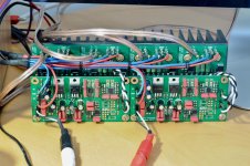
I had a few days off so why not to make another project
This time I have decided to go in some retro design with a small bit of freshness.
Never knew why people were creating quasi designs so I have tried it myself.
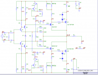
ECC88 input, mosfet VAS cascode and quasi N-mosfet output = Quasi VSHA.
The amp needs a bit further work but so far I am more than satysfied.
A lot of air and micro-details, bass rather warm with quite poor kick, hope higher voltage PSU for the tube front end will sort it out.
Regards
I actually quite like the hybird amp, the schematic you showed also inspires me with new ideas on hybrid amps, thanks
 .
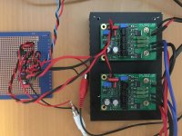
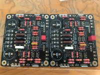
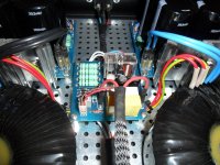
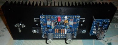
.Stereo active op-amp based 2-way crossover with lateral MOSFET power amps.
Crossover boards are in front, mounted on the power amp boards with standoffs. The whole mess is mounted on a 200x75 heatsink. PCBs for the DC protection & power filter will hopefully arrive Monday.
I've also thrown in a photo of the power amps by themselves - they're an evolution of David Tilbrook's AEM6000.
Schematics and layouts for the crossover PCB is at noiseUnit - transmission line computer speakers.
Attachments
SMY14INCH
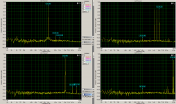
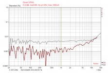
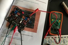
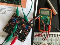
Thanks for kind words. Today I took some measurements and discover a nice small mod that can make the THD spectrum more audiophile kind of way. Bellow oryginal version and modyfied one.
So the plan is that we are making a good amplifier and than we can make it ''worse'' to ''sound'' better
I must say that I am suprised how good simple quasi complementary mosfet output stage can be, and not only on the paper but I really like how it souds.
Regards
Attachments

Last edited:
Your running regulated +-45v?. I had tried to regulate somewhere near this range with 337+317. 317 worked fine but 337 somewhat only wants to regulate somewhere between 46-50v+, any less an it just drops to 30-40v and becomes out of regulation. I guess the 337 went into some sort of self protection cause it sensed higher vout-vin voltage than it handled.Stereo active op-amp based 2-way crossover with lateral MOSFET power amps.
Crossover boards are in front, mounted on the power amp boards with standoffs. The whole mess is mounted on a 200x75 heatsink. PCBs for the DC protection & power filter will hopefully arrive Monday.
I've also thrown in a photo of the power amps by themselves - they're an evolution of David Tilbrook's AEM6000.
Schematics and layouts for the crossover PCB is at noiseUnit - transmission line computer speakers.
I was using a fairchird 337, so i guess if I used another brand it may have worked.
Headphone Amp
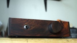
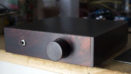
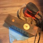
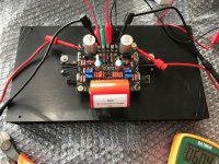
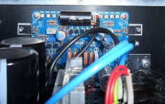
Hi everybody, here is my headphone amp.
It is a Chinese made pcb that seller claimed it is based on Lehman Headphone amp. I do not know anything else about the circuit, all I did was upgrading the coupling caps to Solen, and it sounds amazing.
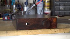
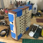
Box was laser cut out of plywood, with Bubinga for side panels and Cocobolo veneer for front.

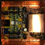
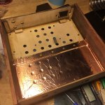
inside, shielded with copper tape, and shielded R-Core Transformer :

Hi everybody, here is my headphone amp.
It is a Chinese made pcb that seller claimed it is based on Lehman Headphone amp. I do not know anything else about the circuit, all I did was upgrading the coupling caps to Solen, and it sounds amazing.
Box was laser cut out of plywood, with Bubinga for side panels and Cocobolo veneer for front.
inside, shielded with copper tape, and shielded R-Core Transformer :
Attachments
Last edited:
Your running regulated +-45v?. I had tried to regulate somewhere near this range with 337+317. 317 worked fine but 337 somewhat only wants to regulate somewhere between 46-50v+, any less an it just drops to 30-40v and becomes out of regulation. I guess the 337 went into some sort of self protection cause it sensed higher vout-vin voltage than it handled.
I was using a fairchird 337, so i guess if I used another brand it may have worked.
No, at the moment I'm running it all at +/-40V from a lab supply. The final supply is a twin 25VAC toroidal. The LM317 & LM337 regs are to provide a +/-15V supply for the opamp stuff.
I like the case of your head amp. Does the heat sink run hot?
Its a ocl head amp? looks like you have a +- regulator and 2 pairs of bd139 as outputs. I like it.
The wiering for inputs on near the transformer seems a little bit off though, could have prboally trimed down the excess wire.
Its a ocl head amp? looks like you have a +- regulator and 2 pairs of bd139 as outputs. I like it.
The wiering for inputs on near the transformer seems a little bit off though, could have prboally trimed down the excess wire.
^^^ Nicely done, congrats.
thanks
I like the case of your head amp. Does the heat sink run hot?
Its a ocl head amp? looks like you have a +- regulator and 2 pairs of bd139 as outputs. I like it.
The wiering for inputs on near the transformer seems a little bit off though, could have prboally trimed down the excess wire.
thank you, it gets warm after normal use, it got abit hot after 30hrs burn in tho.
you r right about OCL, regulator and 4 pair of bd139/140 (2 pairs for each channel).
yeah i could do a much better job for input wires, i m not a patient man
it does not have any audible noise tho.Thanks for your interest.
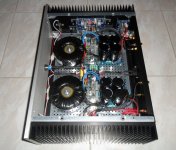
I have been building several First Watt amplifiers (F5, F6, M2) for a couple of years, eventually settling on the M2, because of its relaxed character. But the F5 is - in my humble opinion – still the best of the bunch, when it comes to soundstage, layered depth and details. Ultimately, I have found that music played through the F5 and the other First Watt designs can sometimes be a little lacking when it comes to tonal colors and "flesh". They do details and dynamics very well, but the general sound quality is a bit on the slender side. I came to suspect that the industrial mosfets used the First Watt designs were partly to blame, and began searching for a class A design using lateral mosfets or bipolar transistors.
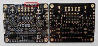
During my search for a new project, I fell over the USSA5 amplifier designed by Fab. Fab is active on this forum, but also on the Quebec DIY forum (quebecdiy.net), where there has been several group buys for PCB’s for the USSA5. You can find a lot more information about the USSA5 design on the Quebec DIY forum.
The USSA5 is a design that has been through several iterations over the years – hence the number 5 suffix. The USSA5 has a CFP input stage with CSS. It uses a set of 2SK2013Y/2SJ313Y as driver transistors. The output transistors are lateral audio mosfets ECF20N20/ ECF20P20.
I managed to buy a set of very well made PCB’s from the last group buy on quebecdiy.net. The PCB’s came with detailed building instructions written by Fab. The amplifier was a pleasure to build, and Fab answered my questions patiently during the process.
So, how does it sound?
The USSA5 has all the best traits of the First Watt F5, combined with a much more natural and organic sound. Good recordings of string quartets come alive in a wonderful and truly holographic manner. The musicians are placed in front of you, and you can sense the resonances of the wooden bodies of the instruments. It is almost magical. Acoustic instruments are portrayed with scale and depth. When listening to more modern pop or rock recordings the USSA5 shows that it is a highly dynamic amplifier with pace, rhythm and a deep and firm bass. Tons of details combined with an addictive natural tonal balance.
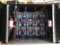
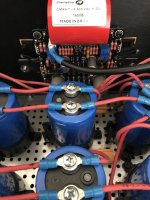
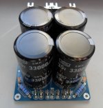
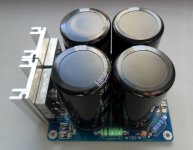
In this project I am re-using the power supply from my First Watt M2. It is a dual mono CLCRC power supply with the power transformers and the first CL stage placed in a separate enclosure.
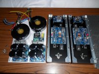
The photos below show the building process. I still need to tidy up some of the wiring, but all is working fine, and there is no noise or hum whatsoever.
If you have read this far, you will know that I am very, very pleased with my USSA5 amplifier. I think you would be too. If you feel like building your own USSA5 amplifier, you should keep an eye out for the next group buy on the Quebec DIY forum.
During my search for a new project, I fell over the USSA5 amplifier designed by Fab. Fab is active on this forum, but also on the Quebec DIY forum (quebecdiy.net), where there has been several group buys for PCB’s for the USSA5. You can find a lot more information about the USSA5 design on the Quebec DIY forum.
The USSA5 is a design that has been through several iterations over the years – hence the number 5 suffix. The USSA5 has a CFP input stage with CSS. It uses a set of 2SK2013Y/2SJ313Y as driver transistors. The output transistors are lateral audio mosfets ECF20N20/ ECF20P20.
I managed to buy a set of very well made PCB’s from the last group buy on quebecdiy.net. The PCB’s came with detailed building instructions written by Fab. The amplifier was a pleasure to build, and Fab answered my questions patiently during the process.
So, how does it sound?
The USSA5 has all the best traits of the First Watt F5, combined with a much more natural and organic sound. Good recordings of string quartets come alive in a wonderful and truly holographic manner. The musicians are placed in front of you, and you can sense the resonances of the wooden bodies of the instruments. It is almost magical. Acoustic instruments are portrayed with scale and depth. When listening to more modern pop or rock recordings the USSA5 shows that it is a highly dynamic amplifier with pace, rhythm and a deep and firm bass. Tons of details combined with an addictive natural tonal balance.
In this project I am re-using the power supply from my First Watt M2. It is a dual mono CLCRC power supply with the power transformers and the first CL stage placed in a separate enclosure.
The photos below show the building process. I still need to tidy up some of the wiring, but all is working fine, and there is no noise or hum whatsoever.
If you have read this far, you will know that I am very, very pleased with my USSA5 amplifier. I think you would be too. If you feel like building your own USSA5 amplifier, you should keep an eye out for the next group buy on the Quebec DIY forum.
Attachments
HH, I like that MASSIVE 4.7uF.
Things are looking good in here as usual!
I'm hoping to sell amplifiers or kits at some stage in my life, so it's a constant investigation into how to keep costs low and how to keep fewer components or what components to keep, etc. I've also found that a very good 50 W amplifier will keep 80% of people happy.
My final design was a 300 W amplifier. A massive thing that cost quite a bit, and took a lot of care constructing. Not to mention the enormous PCB required for that.
So the bug has come back to bite me, and I had to investigate some other cool things. The main reason is that I'm repairing a pair of studio monitors for a friend, and the amplifiers inside aren't any good (never really were anyway). So it's given me the opportunity to try something.
I've design an amplifier which will be good for 50 W in 8 ohms, but it will be built as a 30 W for 4 or 8 ohms off an 18-0-18 transformer. Using higher-power output devices will allow it to be used off a 22-0-22 transformer down to 4 ohms. Anyway, that's not the point. What I've done is design an amplifier which has 2 resistor values. Other than those, it has the output power resistors and output crossover resistors. But the amplifier resistors consist of two values.
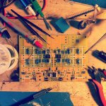
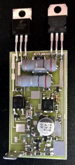
To make this possible, I had to find the right diode for the differential stage current source. I also wanted to keep things small, so I've made it surface-mount all round, and this helps to keep costs down too.
Cost of one PCB is R40. That's less than a 10th of what my huge amplifier's PCB cost. My resistors cost 3c each ($1 gets you about 400), and I only have two values. I use 5 NPN small-signal transistors, and two of each NPN and PNP SMD power transistors for the VAS and drivers. In other words, parts count in terms of number of values of things is extremely low, and cost is very low. Doing this exercise hasn't meant I have had to compromise on quality, and I'm hoping for better specs than my other amplifiers.
Another cool design thing is that I PCB'd the bias transistor and the driver transistor to be in thermal contact via a thick track, so that's pretty cool.
I have attached an image of a completed board (minus two power transistors I'll only receive today, and one connection). It's not the neatest, but it's my first fully-SMD board, hand-soldered with 0.7mm solder and a 3mm tip. In addition, there is no silk-screen or solder mask. Not too bad, I'd say. I also need 3 more Faston tabs.
Things are looking good in here as usual!
I'm hoping to sell amplifiers or kits at some stage in my life, so it's a constant investigation into how to keep costs low and how to keep fewer components or what components to keep, etc. I've also found that a very good 50 W amplifier will keep 80% of people happy.
My final design was a 300 W amplifier. A massive thing that cost quite a bit, and took a lot of care constructing. Not to mention the enormous PCB required for that.
So the bug has come back to bite me, and I had to investigate some other cool things. The main reason is that I'm repairing a pair of studio monitors for a friend, and the amplifiers inside aren't any good (never really were anyway). So it's given me the opportunity to try something.
I've design an amplifier which will be good for 50 W in 8 ohms, but it will be built as a 30 W for 4 or 8 ohms off an 18-0-18 transformer. Using higher-power output devices will allow it to be used off a 22-0-22 transformer down to 4 ohms. Anyway, that's not the point. What I've done is design an amplifier which has 2 resistor values. Other than those, it has the output power resistors and output crossover resistors. But the amplifier resistors consist of two values.
To make this possible, I had to find the right diode for the differential stage current source. I also wanted to keep things small, so I've made it surface-mount all round, and this helps to keep costs down too.
Cost of one PCB is R40. That's less than a 10th of what my huge amplifier's PCB cost. My resistors cost 3c each ($1 gets you about 400), and I only have two values. I use 5 NPN small-signal transistors, and two of each NPN and PNP SMD power transistors for the VAS and drivers. In other words, parts count in terms of number of values of things is extremely low, and cost is very low. Doing this exercise hasn't meant I have had to compromise on quality, and I'm hoping for better specs than my other amplifiers.
Another cool design thing is that I PCB'd the bias transistor and the driver transistor to be in thermal contact via a thick track, so that's pretty cool.
I have attached an image of a completed board (minus two power transistors I'll only receive today, and one connection). It's not the neatest, but it's my first fully-SMD board, hand-soldered with 0.7mm solder and a 3mm tip. In addition, there is no silk-screen or solder mask. Not too bad, I'd say. I also need 3 more Faston tabs.
Attachments
I have been building several First Watt amplifiers (F5, F6, M2) for a couple of years, eventually settling on the M2, because of its relaxed character. <snip>
This amplifier deserves to be more plebic because it is a jewel of sonority, It is that the mosfets are difficult to find but the game is the candle.
A little UP on my USSA-5
Attachments
Project16,
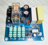
Congratulations on your build, nicely done! And I bet you are using the power boards that you designed yourself. What are the dimensions of the case you have there?
The other smaller boards with relays - I am guessing those are soft start and speaker protection circuits? Which ones are you using? What speakers are you driving with the USSA 5?
Congratulations on your build, nicely done! And I bet you are using the power boards that you designed yourself.
What are the dimensions of the case you have there? The other smaller boards with relays - I am guessing those are soft start and speaker protection circuits? Which ones are you using? What speakers are you driving with the USSA 5?
Last edited:
Nice Work!This amplifier deserves to be more plebic because it is a jewel of sonority, It is that the mosfets are difficult to find but the game is the candle.
A little UP on my USSA-5
Beautiful!
Just a warning! Are these fuse holders suitable for main voltage?
What is the USSA 5?
Last edited:
Of course,YOU are the pcb expert!Sorry ,it's my design .....
Is it for sharing?
Hello AlexSorry ,it's my design .....
Look on the PCB I redesigned, your name is present and on the HS USSA-5 black pcb.
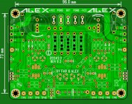
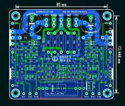
The initial idea to make a PCB with maximum dimensions of 10cm x 10cm for eventually manufacturing at lower cost and it is successful.
However I have made some improvements that are on dimensions, the possibility of putting a larger capacitor and close the resistor (R18) gate M2 which was too far away.
I had a good starting base to work but that is not the version you are presenting.
Attachments
I did not understand all the questions because the online translator gives me anything.Project16,
Congratulations on your build, nicely done! And I bet you are using the power boards that you designed yourself.
The other smaller boards with relays - I am guessing those are soft start and speaker protection circuits? Which ones are you using? What speakers are you driving with the USSA 5?
I actually designed the PSUs to fit the case and it was they who later gave the one I proposed on the buying group.
CRC Power Supply (Class A amplifier)
The small cards are loudspeaker protections with timing but I designed new to SSR with adjustable DC detection, adjustable delay and can receive receive from 15V to 50V.
The third card is also drawn by my care, it is a soft - start with power supply of the led of the switch directly on the sector.
All these assemblies equip my two USSAs, the first to more than two years and I have not encountered any problems.
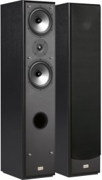
The speakers I use are Elipson Prestige 3 (93 db)
@: thimios
Yes fuses are calibrated for each transformer primary.
Regard's
Attachments
- Home
- Amplifiers
- Solid State
- Post your Solid State pics here