
Member
Joined 2009
Paid Member
I also found the circuit diagram View attachment 607173 that my Dad drew.
this is super cool !!! - a wonderful memory item from your dad - something to treasure for sure.
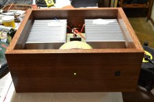
This one sounds better than it looks. I'm almost done with it - need the top and to install the fans.
Beautiful wood work. Is that Mahogany by chance ? Looks very nice.
")
I learned some basic electronics over my winter break and and ordered two jlh amplifier kits to get me started. I appreciate the help I've received here.
For the first amp, I used an old chassis and heatsink from a gw receiver and made a simple wood panel for the front.
For the next amp (not quite finished ), I used some heatsinks from an ampzilla (I scored the heat sinks on the bay) and am using sheet metal for the chassis.
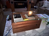
In the photo it's sitting on my next project (klh model five recap).
For the first amp, I used an old chassis and heatsink from a gw receiver and made a simple wood panel for the front.
An externally hosted image should be here but it was not working when we last tested it.
An externally hosted image should be here but it was not working when we last tested it.
For the next amp (not quite finished ), I used some heatsinks from an ampzilla (I scored the heat sinks on the bay) and am using sheet metal for the chassis.
An externally hosted image should be here but it was not working when we last tested it.
In the photo it's sitting on my next project (klh model five recap).
Last edited:
Beautiful wood work. Is that Mahogany by chance ? Looks very nice.
Thank you! Yes, it's mahogany sapele.
Thank you! Yes, it's mahogany sapele.
Very, very nice ! Simply beautiful !
Very, very nice ! Simply beautiful !
Thanks! I'm really happy with it.
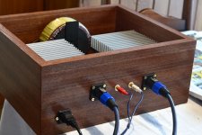
I've finished it now, with glass on top and fans installed.
Attachments
Hello everyone
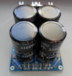
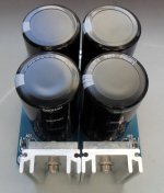
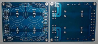
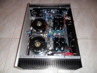
After being enchanted by the sound of Fab's USSA-1, I decided to create version 5 of this superb amplifier.
This new version of a class A amplifier is characterized by more dynamic, higher damping factor and more definite sound, and even if these amplifiers are very close, undeniably the USSA-5 makes its place in the high sound reproduction.
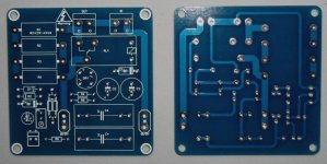
It is therefore with pleasure that I present to you some photos of my last baby with all the PCB that I have to draw, the PCB of the amplifier was designed by Alex MM.
After being enchanted by the sound of Fab's USSA-1, I decided to create version 5 of this superb amplifier.
This new version of a class A amplifier is characterized by more dynamic, higher damping factor and more definite sound, and even if these amplifiers are very close, undeniably the USSA-5 makes its place in the high sound reproduction.
It is therefore with pleasure that I present to you some photos of my last baby with all the PCB that I have to draw, the PCB of the amplifier was designed by Alex MM.
Attachments
-
 Speaker Protect.JPG73.6 KB · Views: 637
 -
 SoftStart3.JPG85.3 KB · Views: 635
 -
 SoftStart2.JPG70.8 KB · Views: 614
 -
 SoftStart1.JPG59.2 KB · Views: 562
 -
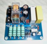
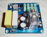
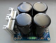 PSU4.JPG59.5 KB · Views: 523
 -
 PSU3.JPG79.7 KB · Views: 501
 -
 PSU2.JPG80 KB · Views: 589
 -
 PSU1.JPG59.2 KB · Views: 735
 -
 USSA-5_2.JPG105.7 KB · Views: 1,730
 -
 USSA-5_1.JPG77.5 KB · Views: 1,300
this is super cool !!! - a wonderful memory item from your dad - something to treasure for sure.
+1, indeed!
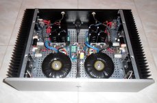
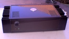
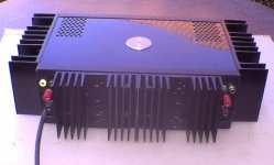
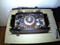
Stereo PowerAmp, build 1979, with fully regulated power supply
Hello all!
I made these Amp in the last 1970s. Since then it is in use every day until now.
It makes about 150watt per channel at 4Ohm
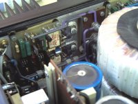
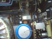
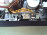
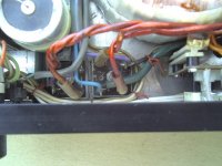
When looking inside it seems i hated wasting space
On the whole rear heatsink is the Power supply regulation and over-current protection.
It is set to +-42 V. The protection switches off permanently at 15A spikes, until the main is switched off for about 3 minutes.
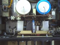
Hello all!
I made these Amp in the last 1970s. Since then it is in use every day until now.
It makes about 150watt per channel at 4Ohm
When looking inside it seems i hated wasting space
On the whole rear heatsink is the Power supply regulation and over-current protection.
It is set to +-42 V. The protection switches off permanently at 15A spikes, until the main is switched off for about 3 minutes.
Attachments

Hello all!
I made these Amp in the last 1970s. Since then it is in use every day until now.
It makes about 150watt per channel at 4Ohm
When looking inside it seems i hated wasting space
On the whole rear heatsink is the Power supply regulation and over-current protection.
It is set to +-42 V. The protection switches off permanently at 15A spikes, until the main is switched off for about 3 minutes.
wow! amazing skills and lot of effort must have gone creating such diy master piece... congratulations sir!
Hello!
Thank you both for the praise words, but do not exaggerate.
I am better in mechanical constructions than in the development of electronic circuits. Everything is based on very simple circuits.
The mentioned "effort" at that time was mainly that I as a hobbyist could not as easy access to components and their data as today on the Internet. Therefore the circuit development was partly based on trial and error until the right parts were found, especially at the power supply.
- Home
- Amplifiers
- Solid State
- Post your Solid State pics here