Audiosan
The idea is to get the most efficient heat transfer possible. This is way more important than having the devices run at the exact same temperature - heat kills. I many times have seen devices mounted on a tiny little piece of 1/4" stock that is then mounted to a heat sink resulting in much higher temperature of devices than if mounted in the fashion above.
Good Listening
Peter
I actually did this with 1 pair per heatsink. It did not work out too well.
One pair would always become the "current hog". Thermal stability was never good
until I moved both the pairs to their own heatsink.
PS- on separate heatsinks, the pair with the drivers/Vbe would always run the coolest.
Swapping the pairs made no difference.
OS
One pair would always become the "current hog". Thermal stability was never good
until I moved both the pairs to their own heatsink.
PS- on separate heatsinks, the pair with the drivers/Vbe would always run the coolest.
Swapping the pairs made no difference.
OS
Have made 100s of amplifiers this way and have never had an issue with thermal stability, the sinks very quickly become the same temperature. In addition I place the bias FET on the heat sink for thermal tracking, works like a champ. That being said I only use MOS FETS for outputs, Bipolar output transistors may react different.
Good Listening
Peter
Good Listening
Peter
Sorry I don't have any links.
Both Avvid, Wakefield and another? have an app note that describes the optimum layout.
I have seen more, but it was such a long time ago.
If I remember nearly correctly, two rows are roughly 25% up and 60% up from the bottom. Note how close the upper row is to the middle.
Remember that the holes generally do not coincide with the centroid of the heat transfer interface, unless you use clamps.
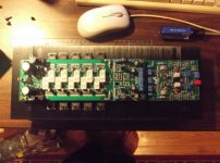
That would be good if I had a 5U heatsink. I live small , just a 3U 140 X 360 X
60mm. (below).
Here I would have either 3 pair MT-200 or 5 pair MT-100 , not much room.
On this one the P channels would be at 25% , N-channels 75%. If I dropped this to
15%/65%, would I see a massive difference ? I would still have hotter N than P
devices , regardless ??
OS
Attachments
optimum is not a lot cooler.
It just a bit cooler than non optimum.
moving the two groups down slightly will bring the top row temperature down closer to the bottom.
I don't know whether 20% 70% is right or 15% 65%.
software that lets you experiment with a model would give a better clue than me guessing.
It just a bit cooler than non optimum.
moving the two groups down slightly will bring the top row temperature down closer to the bottom.
I don't know whether 20% 70% is right or 15% 65%.
software that lets you experiment with a model would give a better clue than me guessing.
I remember reading somewhere that taller heatsinks >300mm with vertical fins can exploit natural convection when the devices are placed asymmetrically. The idea is to create a temperature differential between top and bottom to start a circular convection of 0.8-1.2cfm and that is sufficient disturbance to outperform the inefficient heat distribution on the metal. Anyone here ever try this?
Maybe so but perhaps that temperature difference may not be sufficient to induce the convection effect described if it isn't asymmetrical. The convection loop radius may require the 300mm height or it may not form. My saved link to this is dead. It had diagrams and math explaining the process.
Last edited:
It does matter.
The top row of devices will run much hotter than the bottom row devices.
10degrees will make a big difference to temperature de-rated SOAR, if you are running at Tc=70°C that becomes 80 for the upper row.
If it were Tc=50°C that became 55, then there is not much difference.
It does matter.
The top row of devices will run much hotter than the bottom row devices.
10degrees will make a big difference to temperature de-rated SOAR, if you are running at Tc=70°C that becomes 80 for the upper row.
If it were Tc=50°C that became 55, then there is not much difference.
Reply from Mark Haywood, you have got things mixed up! The heatsink you are referring to is not mine. For my class A 8 watt stereo amplifier I use a Quad 405 heatsink not as Quad used it, but in a roof position with my power transistors screwed to the bottom of the two fastening protruburances. Best regards.
 .
.1600 watt peak class AB amplifier.
An externally hosted image should be here but it was not working when we last tested it.
Why always? Which is hotter, top or bottom?AndrewT said:A vertically aligned heatsink will always have a temperature difference along the height dimension. this does not depend on the sink being >300mm tall.
Air entering the slots between the fins is at ambient temperature (Ta).
The fins at the BOTTOM are cooled by Ta air.
As the warmed less dense air rises it cools the adjacent fin/s
These (higher up) fins are cooled by air that is above Ta.
By the time the air has traveled up past the fins, the air is at maximum temperature Ta++
The fins at the TOP are being cooled by Ta++ air. These fins are hotter than the fins at the bottom. Because delta Ts-a is lower.
There is further complication:
The backplate is not at constant temperature, i.e. it is not isothermal.
The hottest part is directly in contact with the device emitting heat.
As the heat travels outwards (sideways as well as through the thickness) it passes through Thermal Resistance.
The further the heat travels the more the temperature drops.
Out at the sides the sink backplate can be many C degrees cooler than under the device.
At the top and the bottom, the backplate can be many C degrees cooler than under the device.
Combine these two and you will find that the corners of the heatsink are the coolest points on the backplate.
Any fins connected to these "cooler" parts will not transfer as much heat as the hotter parts of the sink.
More complication:
Radiation also cools the heatsink.
The area of the FIN END projecting DOWN radiates heat into the environment.
The area of the fin end facing up radiates heat into the environment.
The side of the fin facing sideways radiates heat into the environment.
The black body AREA of the WHOLE outside face of the heatsink (same area as the backplate) radiates heat into the environment.
The backplate area facing into the chassis radiates heat into the environment. This heats up many of the internal components. Two thin but separated layers of polished aluminium (Bakofoil) massively reduces the heating of internal components from radiated heat emitted by the heatsink.
There are at least two free Thermal Calculators that let you see the temperature variations around a heatsink.
Last edited:
All that you describe above is subject to the mounted position(s) of the devices. If there are calculators then there will be a way to distribute the heat so top and bottom is equal. This seems to refute your initial statement that prompted the question to you. Also, the implication that there will always be a circular convection with vertical fins no matter how short also seems wrong because of entropy. The temp differential and convection loop need to be large enough to force the surrounding air into an orderly flow. A tighter radius of airflow makes creating an orderly loop more difficult to achieve.
Nania,
warmed air rises due to density difference.
Where do circles come in?
at least one of us is misunderstanding the other.This seems to refute your initial statement that prompted the question to you
a circular convection
what are you talking about?tighter radius of airflow
warmed air rises due to density difference.
Where do circles come in?
I said in post3762
do you have evidence that my statement is wrong?
Nania,The top row of devices will run much hotter than the bottom row devices.
do you have evidence that my statement is wrong?
When there is a temperature differential and a distance between the heat sources a circular motion of air effect can be produced (similar to all natural torque patterns-see torus). The heat dispersion is not a linear vector so it will not go straight up as you imply and depending on where the sources are mounted, the top of the heat sink does not have to be hotter. When the distance between the heat sources is short, stable vector angles cannot be formed and therefore no support for the torus so the distance matters. To say heat will rise gives an incomplete and faulty description of what is actually happening and will make someone miss an opportunity to try something innovative.
- Home
- Amplifiers
- Solid State
- Post your Solid State pics here