Forgot to say that this one of the best sounding amps that I have ever built.

anatech
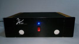
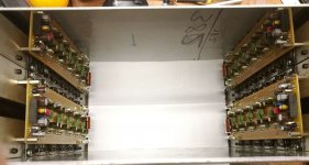
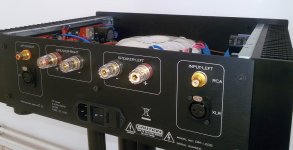
I am making enclosure from stainless steel and it is reflecting nicely two channels into the 4ch.
If I'll remove floor protection foil I will get 6 channel amp
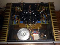
I am using 5 pairs of fast 100W sankens at the output, power supply voltage will be approx 2x 50VDC and a lot of bias. Hope I will get nice 2x 100W out of it.
Best regards
Peter
I am making enclosure from stainless steel and it is reflecting nicely two channels into the 4ch.
If I'll remove floor protection foil I will get 6 channel amp
I am using 5 pairs of fast 100W sankens at the output, power supply voltage will be approx 2x 50VDC and a lot of bias. Hope I will get nice 2x 100W out of it.
Best regards
Peter
finally...
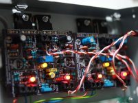
Here is my build.
It took some time but here it is.
Some specialties
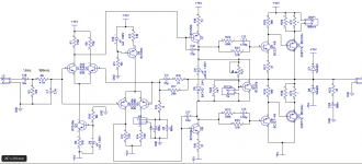
- Double-differential input stage
- LED + Schottky diode as Bias Voltage generator
- NTC reduces Bias voltage to prevent thermal runaway. This works well with the BAT43 curve and R20.
I feed 21V not 15V.
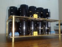
Caps made in W-Germany (as said it took some time).
I recycled the housing of a Sat receiver that broke just few weeks ago... not too pretty but better than loose PCBs.
It sounds awesome...
Here is my build.
It took some time but here it is.
Some specialties
- Double-differential input stage
- LED + Schottky diode as Bias Voltage generator
- NTC reduces Bias voltage to prevent thermal runaway. This works well with the BAT43 curve and R20.
I feed 21V not 15V.
Caps made in W-Germany (as said it took some time).
I recycled the housing of a Sat receiver that broke just few weeks ago... not too pretty but better than loose PCBs.
It sounds awesome...
Attachments
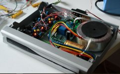
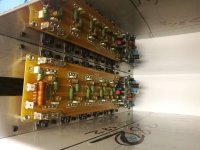
are you heatshinking on the iron steel chassis?
It sure looks like it. Configured this way, only modest outputs can be expected before the transistors overheat. You need to provide some sort of thermal shut off to prevent them from being damaged if that happens.
^^^ very nice build.
thanks
are you heatshinking on the iron steel chassis?
 I got caught quickly for that I took that housing just because it was there. Unfortunately I cannot heatsink to the sides or the rear
 It sure looks like it. Configured this way, only modest outputs can be expected before the transistors overheat. You need to provide some sort of thermal shut off to prevent them from being damaged if that happens.
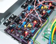
Thanks for your comment on this! And for caring about my house!! But I should explain my point of view. Some heat is generated by Bias current, some by the actual waveform.
Bias:
In this design, the NTCs will reduce the Bias current quasi linearly starting at 40°C to 60°C, like between 40 down to 10mA, and ultimately turn it off at 75°C (setpoints adjusted by R21). This keeps temperature moderate in normal operation - and: no thermal runaway. I am quite sure the big heatsinks seen around are because the standard Bias voltage generator still allow a certain thermal runaway, at least according to my own tests. With this my outputs did run hot! And I added a galvanometer at R31 (see Disp1 in the schematic) to understand this. So I redesigned the controller considering the Bias load curve D6+D11 (4mA = 2.3V and 1mA = 2.0V) where these 3mA are "eaten" by Q13, according to the temperature setpoints of the NTC and R20, R21. You may add a collector resistance to Q13 to avoid complete Bias turnoff, but in practice I never reached beyond 60°C even with sinewaves on 4Ohm resistors.
Waveform:
With 21V and 4Ohm rated speakers. I reach a maximum of 45W speaker output around 4 Amps. But I only reach a maximum in power losses on the transistor at 2 Amps DC, which is 24 Watt DC Transistor losses. At AC and since there are two transistors this is only like 9 W transistor losses. I used Tip36C which allows 125°C at my theoretical maximum of 25 Watt. I tested it with Music at like 75% level (earbuds needed
) and it stays quite cool. I suppose this changes with +-35V or higher supplies.
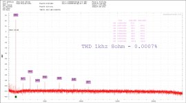
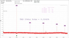
I think so. I am not too interested about this function because THD at 1khz and 20khz say everything. I'll testing the amplifier at IMD (19+20)khz 1:1 but I do not think there will be any problems because the slew-rate it is almost 80V/us.
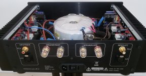
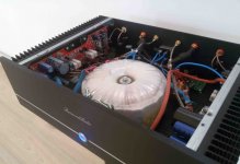
The icing on the cake it is the transformer. It has 600VA at 9,6kg, B=1T, 3 belly belts, the first and the second are from silicone sheet and the third is from mu-metall.
The icing on the cake it is the transformer. It has 600VA at 9,6kg, B=1T, 3 belly belts, the first and the second are from silicone sheet and the third is from mu-metall.
Last edited:
The transformer was designed by me and customed executed by PETRA TOROID
Interesting circuit.Here is my build.....
All Quasi-comp-Amps i saw before, were built with NPN output Transistors.
(May be, i haven't seen enough)
What do you use the J4 connector for?
- Home
- Amplifiers
- Solid State
- Post your Solid State pics here