Fancy parts.
Not many left; they don't make them anymore, if I'm not mistaken.
-Henry
.... i am missing something here ...is this amplifier working without capacitors ? cause i cant see them in the foto ...still tha cables seem to be connected on boardsI had an extra set of SymAsym boards and I decided to use them to rebuild an old amplifier. The layout is a bit unfortunate, but workable. Since the heatsink assembly was made for TO-3 transistors, I chose to use a set of 2ST2121/5949 outputs. The amplifier is unconditionally stable and has a 450kHz bandwidth.
Here we are, work in progress.
-Henry
have i missed something ?
EDIT :looking at it once more seems that twisted cables are coming from the bridge to the boards and then another set of cables that is supposed to go to the capacitor banks ?
if you are planing to do this be aware that is a very bad practice .... from trafo you to bridge then from bridge to caps and then from caps to amp ...
let us know
kind regards sakis
Last edited:
finished velleman k4010
hi there...
i am building velleman k4010 kits.
but i am having a problem with mine,
sound is pretty good but there are hum (at bass spk) and distortion (at treeble spk),
can anyone suggest what should i do?
this is my finished amp pics:
i am having a ground loop problem with this finished amp.
hi there...
i am building velleman k4010 kits.
but i am having a problem with mine,
sound is pretty good but there are hum (at bass spk) and distortion (at treeble spk),
can anyone suggest what should i do?
this is my finished amp pics:
An externally hosted image should be here but it was not working when we last tested it.
An externally hosted image should be here but it was not working when we last tested it.
An externally hosted image should be here but it was not working when we last tested it.
An externally hosted image should be here but it was not working when we last tested it.
An externally hosted image should be here but it was not working when we last tested it.
An externally hosted image should be here but it was not working when we last tested it.
An externally hosted image should be here but it was not working when we last tested it.
An externally hosted image should be here but it was not working when we last tested it.
i am having a ground loop problem with this finished amp.
.... i am missing something here ...is this amplifier working without capacitors ? cause i cant see them in the foto ...still tha cables seem to be connected on boards
have i missed something ?
EDIT :looking at it once more seems that twisted cables are coming from the bridge to the boards and then another set of cables that is supposed to go to the capacitor banks ?
if you are planing to do this be aware that is a very bad practice .... from trafo you to bridge then from bridge to caps and then from caps to amp ...
let us know
kind regards sakis
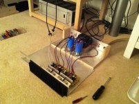
I understand your confusion! No, as I said, it's a work in progress. Lots of wires still waiting to be connected, plus the rectifier/capacitor board.
Here's a picture of the test setup I used to verify the performance with the ST transistors.
-Henry
Attachments
.... i am missing something here ...is this amplifier working without capacitors ? cause i cant see them in the foto ...still tha cables seem to be connected on boards
have i missed something ?
As Henry clearly states, "work in progress".
Since no capacitor bank has been installed and wires are not connected, this is not yet a working amp!
A closer look and everything is clear.
Regards,
Max.
don't make them anymore
Remakes of the Toshiba A2121/C5949, in a different jacket.
Similar deal as OnSemi with MJL1302/3281 and the Toshiba A1302/C3281 (A1943/C5200)
ST likely picked the wrong turn with the TO-3 package, they've been active production for a very short period.
HP,
the test assembly shows your PSU connections.
You have at least two tappings from the PSU Zero Volts.
One on the left cap to the left channel and one on the right cap to the right channel. This is wrong.
The three wires from the PSU to each amplifier, zero volts +ve -ve, should be twisted as a triplet and taken to the amplifier as that triplet. At the amplifiers (since it's two channel) the triplet is Y split to form two sets of triplets. One set to each amplifier. Keep these final triplets as short as possible and use low resistance wire in the Zero volts between the two amp boards.
Wengtech
Your amp looks to be slightly older revision of mine, i cant see any delay on relays or dc protection circuits.
I goy lucky with mine and it fired up first time and has been running great for a month or so, i have some scans of the latest manuals and component additions if they are any use to you.
best regards james
can you show me pcb.I had an extra set of SymAsym boards and I decided to use them to rebuild an old amplifier. The layout is a bit unfortunate, but workable. Since the heatsink assembly was made for TO-3 transistors, I chose to use a set of 2ST2121/5949 outputs. The amplifier is unconditionally stable and has a 450kHz bandwidth.
Here we are, work in progress.
-Henry
thanking you
can you show me pcb.
thanking you
The boards are the original SymAsym 5.3 design, as described here:
[wiki=http://www.lf-pro.net/mbittner/Sym5_Webpage/symasym5_3.html]%[/wiki]
I kept the board as is, but used the TO-3 outputs on sockets with short wires connecting them to the board.
Here is another diyAudio thread about a redesign of this PCB specifically to use TO-3 outputs:
[wiki=http://www.diyaudio.com/forums/group-buys/187592-3-symasym.html]%[/wiki]
With no offense intended to Mr. Bittner, who has designed by all accounts a very fine circuit, his original PCB design had some shortcomings and a number of improved layouts have been published. For instance, I have built AAK's dual output transistor version of the SymAsym with good results. If you search the forum you can easily find these discussions.
-Henry
HP,
the test assembly shows your PSU connections.
You have at least two tappings from the PSU Zero Volts.
One on the left cap to the left channel and one on the right cap to the right channel. This is wrong.
The three wires from the PSU to each amplifier, zero volts +ve -ve, should be twisted as a triplet and taken to the amplifier as that triplet. At the amplifiers (since it's two channel) the triplet is Y split to form two sets of triplets. One set to each amplifier. Keep these final triplets as short as possible and use low resistance wire in the Zero volts between the two amp boards.
Thank you for your very correct observation. If you were to zoom in on a high-resolution version of the photo, you would see the stubs of black wires adjacent to the transformer center tap connection on the bus wire between the capacitors. This is where the circuit board power grounds were originally connected. For a test lash-up, I was not concerned about punctillious grounding.
FWIW, the chassis with the power supply was a breadboard that I used for testing the complete amplifier before I eventually built this:
[wiki=http://www.diyaudio.com/forums/solid-state/96192-post-your-solid-state-pics-here-226.html#post2907972]%[/wiki]
The final version of my latest amplifier will have a dual-mono power supply with correct grounding and modern filter capacitors. (Those Sprague blue cans are 30 years old!)
-Henry
HP,
The three wires from the PSU to each amplifier, zero volts +ve -ve, should be twisted as a triplet and taken to the amplifier as that triplet. At the amplifiers (since it's two channel) the triplet is Y split to form two sets of triplets. One set to each amplifier. Keep these final triplets as short as possible and use low resistance wire in the Zero volts between the two amp boards.
triplets ? i don't think so Andrew always ground is supposed to be out of the "twisting" twist rails together yes but ground never with them .
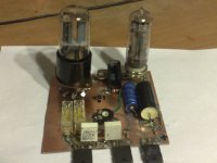
some little test with a hybride, mosfet dc driven by a 6C19 and a srpp 6N8, the 6C19 is not a cathodefollower but a plate follower driving the mosfets, I did need a high current low mu tube because of the mosfet capacity and to not to use feedback.
The printed circuit is made with a dremel, because it is just a tryout how a hybride without a cathodefollower sounds, this one has none, the 6n8 is not yet soldered that happens today.
The printed circuit is made with a dremel, because it is just a tryout how a hybride without a cathodefollower sounds, this one has none, the 6n8 is not yet soldered that happens today.
Attachments
some little test with a hybride, mosfet dc driven by a 6C19 and a srpp 6N8, the 6C19 is not a cathodefollower but a plate follower driving the mosfets, I did need a high current low mu tube because of the mosfet capacity and to not to use feedback.
The printed circuit is made with a dremel, because it is just a tryout how a hybride without a cathodefollower sounds, this one has none, the 6n8 is not yet soldered that happens today.
Wow, far out. I'm a great believer in hybrid amps. I'm guessing it should sound smooth.
There are some pics of mine on another thread.
http://www.diyaudio.com/forums/solid-state/208506-hybrid-diy-cct-lm3886-6n11.html#post2956841
It's as ugly as a Borg mothercube (I build speakers really...
http://alacrityaudio.files.wordpress.com/2012/03/caterthun-f1.jpg?w=640&h=1031
) but it scares me to death. It'll creep up on you from nowhere and leave you shell-shocked, wondering just how did it do that...
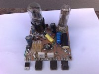
I have now everything soldered, how it sound I do not now yet, a version of it with cathode follower works here for already 4 years, still with wires and no pcb.
this has a p follower to test, it is a pcb made with dremel, and some old parts for testing it, It is ready for the big test after cooling is ready, LM350 is also on board now with supply.
Do it work nicely I make a board for it.
this has a p follower to test, it is a pcb made with dremel, and some old parts for testing it, It is ready for the big test after cooling is ready, LM350 is also on board now with supply.
Do it work nicely I make a board for it.
Attachments
- Home
- Amplifiers
- Solid State
- Post your Solid State pics here