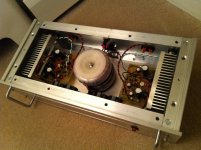
Here's my little b24
Sounds really good!
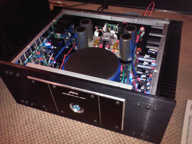
Fun to build but I should have taken a 400mm chassis instead of the 300mm. It was too tight!
Do
Wow, very nice build! I did a search after it, for me AMB is new.
Balanced amps are rare in the diy world, they intrique me.
Any change to send me the schematic with a PM?
Greetz
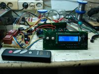
PGA2310 Line Preamplifier
This is my last preamplifier project. I simply started an experiment with the PGA2310 that finally led me in a complete project - as usually .
A summary of its properties:
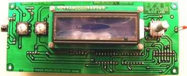
1) It can be managed either locally thru 2 push switches and a rotary encoder, or remotely from a RC5 compatible universal remote control handset. Includes 5 Inputs, 1 Main Output and 1 Record Output. Control functions are the 7 basic: a)Power On/Stand By b) Mute c)Volume increment d)Volume decrement e)Balance f)Input selection in forward sequence and g)Input selection in backward sequence. All these functions are also supported by the remote control except the Balance.
2) The analog signal process is obtained thru a PGA2310 programmable volume control IC. Voltage gain can be adjusted from -95 up to +6dB in steps of 1dB. Volume control IC is buffered from input and output devices like CD players and Power amplifiers from four LME49710 operational amplifiers configured as voltage followers.
3) Separate power supplies are used for Analog and Digital section..
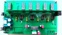
4) Input selection and Output Mute functions are obtained with the use of high quality Latching relays. The Stand By function (i.e. enable – disable the analog power supply transformer) is also obtained with a powerful SPNO/10A Latching relay. Latching type relays ensure both power saving and noise immunity on audio signal as their coils are inactive for most time. A momentary voltage pulse of 15ms is enough to change the location of their contacts.
5) The whole device is managed by a PIC16F887 microcontroller. The appropriate program code has obtained with the use of the powerful Visual Programming Software FlowCode v5 of Matrix Multimedia.
For a more detailed description, schematics and an offer to you my good friends (a free copy of code in hex format so you can program your PIC16F887 with any type programming device you own") ) please here: Matrix Multimedia user forums • View topic - Hi-Fi audio preamplifier using Burr-Brown PGA2310
) please here: Matrix Multimedia user forums • View topic - Hi-Fi audio preamplifier using Burr-Brown PGA2310
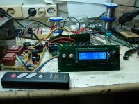
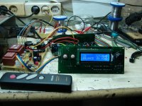
Here some pictures showing its functionality
This is my last preamplifier project. I simply started an experiment with the PGA2310 that finally led me in a complete project - as usually .
A summary of its properties:
1) It can be managed either locally thru 2 push switches and a rotary encoder, or remotely from a RC5 compatible universal remote control handset. Includes 5 Inputs, 1 Main Output and 1 Record Output. Control functions are the 7 basic: a)Power On/Stand By b) Mute c)Volume increment d)Volume decrement e)Balance f)Input selection in forward sequence and g)Input selection in backward sequence. All these functions are also supported by the remote control except the Balance.
2) The analog signal process is obtained thru a PGA2310 programmable volume control IC. Voltage gain can be adjusted from -95 up to +6dB in steps of 1dB. Volume control IC is buffered from input and output devices like CD players and Power amplifiers from four LME49710 operational amplifiers configured as voltage followers.
3) Separate power supplies are used for Analog and Digital section..
4) Input selection and Output Mute functions are obtained with the use of high quality Latching relays. The Stand By function (i.e. enable – disable the analog power supply transformer) is also obtained with a powerful SPNO/10A Latching relay. Latching type relays ensure both power saving and noise immunity on audio signal as their coils are inactive for most time. A momentary voltage pulse of 15ms is enough to change the location of their contacts.
5) The whole device is managed by a PIC16F887 microcontroller. The appropriate program code has obtained with the use of the powerful Visual Programming Software FlowCode v5 of Matrix Multimedia.
For a more detailed description, schematics and an offer to you my good friends (a free copy of code in hex format so you can program your PIC16F887 with any type programming device you own
) please here: Matrix Multimedia user forums • View topic - Hi-Fi audio preamplifier using Burr-Brown PGA2310 Here some pictures showing its functionality
Attachments
Last edited:
PGA2310 Line Preamplifier - 2
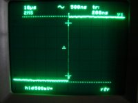
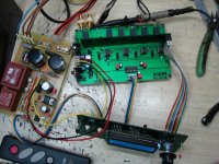
Here is a general view of project, and a very - very interesting second picture. In the last you can see the performance of preamplifier. In this DSO screen shot it is obvious the rise time of signal at the output of preamplifier. After a pass thru 3 ICs: LME49710-->PGA2310-->LME49710 the square wave (for a total gain of 0dB) rise time has increased just to 200nsec! That means bandwidth: BW = 0.34 / 200nsec = 1.7MHz with negligible overshoot.
Fotis
Attachments
Quad owners : You may hate my guts
Sorry but this was done on a costumer's request ...one way or another is reversible
happy regards
sakis
Jeez, now that looks terrible. An honorable audio fanatic would have declined!
;-)
LOL
Wow, very nice build! I did a search after it, for me AMB is new.
Balanced amps are rare in the diy world, they intrique me.
Any change to send me the schematic with a PM?
Greetz
Hi Bensen,
You can go on AMB's web site and send an email to Ti. Schematics are available on demand and I wouldn't want to send them without authorization.
I'm sure you'll get them without any issues. Ti is a great guy!
Ciao!
Do
Quad owners : You may hate my guts
Sorry but this was done on a costumer's request ...one way or another is reversible
happy regards
sakis
Jeez, now that looks terrible. An honorable audio fanatic would have declined!
;-)
LOL
Well... Not that it is an aesthetically great looking amp anyways....
I think that functionality is better this way
Do
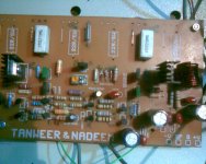
I made this on my weekend. 400w power amp
I made this on my weekend. 400w power amp.
Now i want to make Peavy's professional amp (Maximum Watts) . Plz share (you can email me at kamran.yousafb@gmail.com) its schematic if any body have Thanks.
I made this on my weekend. 400w power amp.
Now i want to make Peavy's professional amp (Maximum Watts) . Plz share (you can email me at kamran.yousafb@gmail.com) its schematic if any body have Thanks.
Attachments
Please share its Schematic with parts list
Sir,
Can u plz share its Schematic with parts list & PCB (Just power amp's not protection circuit etc) etc at kamran.yousafb@gmail.com
Wow, very nice build! I did a search after it, for me AMB is new.
Balanced amps are rare in the diy world, they intrique me.
Any change to send me the schematic with a PM?
Greetz
Sir,
Can u plz share its Schematic with parts list & PCB (Just power amp's not protection circuit etc) etc at kamran.yousafb@gmail.com
Sir,
Can u plz share its Schematic with parts list & PCB (Just power amp's not protection circuit etc) etc at kamran.yousafb@gmail.com
Hi kamranyousaf,
You can go to AMB's web site here The β24 Fully-differential Power Amplifier and request the schematics. Ti has a BOM for it as well. You can access their store and buy the PCBs and some of the parts if needed.
Thanks
Do
Hi kamranyousaf,
You can go to AMB's web site here The β24 Fully-differential Power Amplifier and request the schematics. Ti has a BOM for it as well. You can access their store and buy the PCBs and some of the parts if needed.
Thanks
Do
Thanks Dear ,
Have you tried their schematics & pcb's etc.
Thanks Dear ,
Have you tried their schematics & pcb's etc.
Yep,
The version I built is using their PCBs. It is four layer so it would be quite hard to do this properly with only two layers.
The price is good for this level of quality
Don't hesitate, just buy! You'll love it
Do
Another L20 amplifier
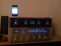
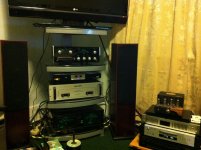
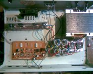
This is my second L20 amplfier with 10 less volts in the transformer secondaries but 1 ampere of current more than the previous amp had. This amp runs cool while the last one runs quite warm. Both have the same size heat sinks. The L20 is a fairly popular circuit board offered for sale by several Ebay vendors. I liked my first one and decided to build another using dual Hammond 182F30 transformers that I had on hand. I substituted the new L20 for the old L20 and did not hear a difference. The old L20 had bumped an aging Carver TFM-15b which was relegated to driving the rear speakers in my 5.1 system. The new L20 bumps the Carver once again. The Carver will be appearing on Craigslist soon.
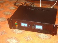
This amp incorporates a 'soft start' circuit that activates when the red button is pressed on the front. I however, want to know when AC power is reaching the amplifier and I wanted to be able to turn off the AC to the amplifier without shutting down my whole system so hence the toggle switch and amber light. The amber light signifies that AC is applied to the amp, the green light signifies the red button has been pushed and the amp is completely powered up. The soft start circuit also has 2 temperature sensors that attach to the heat sink and shuts down the AC if the heat sink reaches 75 C. There is also a speaker relay circuit which mutes the amp at start up and shut down.
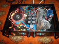
The meters in front are connected to the speaker output by JLM (of Australia) buffer boards. The level controls attenuate the input signals. I used 100K Alps because that is what I had, but 50K would be better suited. Adding meters and level controls is a royal pain and very time consuming and I see why most builders forgo this. Front power switches are also a pain. But I find these features to be very useful and hard to live without.
To save space, I stacked the power supply boards and the toroidal transformers. Is this a bad idea? Comment would be welcome on the pros and cons of this.
I am quite pleased with sound. I will probably build another L20.
This is my second L20 amplfier with 10 less volts in the transformer secondaries but 1 ampere of current more than the previous amp had. This amp runs cool while the last one runs quite warm. Both have the same size heat sinks. The L20 is a fairly popular circuit board offered for sale by several Ebay vendors. I liked my first one and decided to build another using dual Hammond 182F30 transformers that I had on hand. I substituted the new L20 for the old L20 and did not hear a difference. The old L20 had bumped an aging Carver TFM-15b which was relegated to driving the rear speakers in my 5.1 system. The new L20 bumps the Carver once again. The Carver will be appearing on Craigslist soon.
This amp incorporates a 'soft start' circuit that activates when the red button is pressed on the front. I however, want to know when AC power is reaching the amplifier and I wanted to be able to turn off the AC to the amplifier without shutting down my whole system so hence the toggle switch and amber light. The amber light signifies that AC is applied to the amp, the green light signifies the red button has been pushed and the amp is completely powered up. The soft start circuit also has 2 temperature sensors that attach to the heat sink and shuts down the AC if the heat sink reaches 75 C. There is also a speaker relay circuit which mutes the amp at start up and shut down.
The meters in front are connected to the speaker output by JLM (of Australia) buffer boards. The level controls attenuate the input signals. I used 100K Alps because that is what I had, but 50K would be better suited. Adding meters and level controls is a royal pain and very time consuming and I see why most builders forgo this. Front power switches are also a pain. But I find these features to be very useful and hard to live without.
To save space, I stacked the power supply boards and the toroidal transformers. Is this a bad idea? Comment would be welcome on the pros and cons of this.
I am quite pleased with sound. I will probably build another L20.
Attachments
Yep,
The version I built is using their PCBs. It is four layer so it would be quite hard to do this properly with only two layers.
The price is good for this level of quality
Don't hesitate, just buy! You'll love it
Do
Would you please share it with me.
This is my second L20 amplfier with 10 less volts in the transformer secondaries but 1 ampere of current more than the previous amp had. This amp runs cool while the last one runs quite warm. Both have the same size heat sinks. The L20 is a fairly popular circuit board offered for sale by several Ebay vendors. I liked my first one and decided to build another using dual Hammond 182F30 transformers that I had on hand. I substituted the new L20 for the old L20 and did not hear a difference. The old L20 had bumped an aging Carver TFM-15b which was relegated to driving the rear speakers in my 5.1 system. The new L20 bumps the Carver once again. The Carver will be appearing on Craigslist soon.
This amp incorporates a 'soft start' circuit that activates when the red button is pressed on the front. I however, want to know when AC power is reaching the amplifier and I wanted to be able to turn off the AC to the amplifier without shutting down my whole system so hence the toggle switch and amber light. The amber light signifies that AC is applied to the amp, the green light signifies the red button has been pushed and the amp is completely powered up. The soft start circuit also has 2 temperature sensors that attach to the heat sink and shuts down the AC if the heat sink reaches 75 C. There is also a speaker relay circuit which mutes the amp at start up and shut down.
The meters in front are connected to the speaker output by JLM (of Australia) buffer boards. The level controls attenuate the input signals. I used 100K Alps because that is what I had, but 50K would be better suited. Adding meters and level controls is a royal pain and very time consuming and I see why most builders forgo this. Front power switches are also a pain. But I find these features to be very useful and hard to live without.
To save space, I stacked the power supply boards and the toroidal transformers. Is this a bad idea? Comment would be welcome on the pros and cons of this.
I am quite pleased with sound. I will probably build another L20.
Sir,
Would you please share its schematic Thanks.
Symasym 5.3
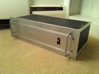
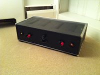
Symasym 5.3 based on the original PCB artwork. I extensively reworked a surplus chassis from an old electron microscope controller to build the box. Sounds nice.
-Henry
Symasym 5.3 based on the original PCB artwork. I extensively reworked a surplus chassis from an old electron microscope controller to build the box. Sounds nice.
-Henry
Attachments
- Home
- Amplifiers
- Solid State
- Post your Solid State pics here