Hi, all
I'm stitting here with my amp, and playing with different input voltage rails. I've noticed a 25% reduction in output noise levels with a double in rail voltages. ( .0125 vRMS @ +-20 Volts, and .0094 vRMS @ +-50 volts.)
Currently, The higher voltage rails increase the bias currents on diff pair and grounded emitter stages.
This is a subject I've not really encountered before, and was wondering how bias voltages/currents affect noise levels in transistors, or has anyone ever looked into this.
-Dan
Well, the bias can effect the crossover distortion.dkemppai said:Hi, all
I'm stitting here with my amp, and playing with different input voltage rails. I've noticed a 25% reduction in output noise levels with a double in rail voltages. ( .0125 vRMS @ +-20 Volts, and .0094 vRMS @ +-50 volts.)
Currently, The higher voltage rails increase the bias currents on diff pair and grounded emitter stages.
This is a subject I've not really encountered before, and was wondering how bias voltages/currents affect noise levels in transistors, or has anyone ever looked into this.
-Dan
also the current sorces, can make
the input be balanced (equal current in each transistor)
at a certain voltage level.
The difference should be kept as low as within a couple of %
between those 2 transistors! For optimal performance.
A higher voltage gives less of a saturation in some of the transistors.
Can make them behave better. Especially in the voltage amp stage.
At dynamic signals.
---------------------------------------------
This is what I can come to think of.
Surely there must be others, who know much better.

We can wait til Nelson comes back.
I would think he will have a valid opinion.
How do you measure the noise?
It is with no input signal?
How is distortion with sinus signal?
Is it changing with the supply voltage, as well?
/halo - the homemade expert on noise
Re: Re: Weird, Less noise with more voltage.
Bias for AB output devices is directly across several diodes. One Zener, and 3 standard diodes. My output devices are mosfet, so voltage needs to be around 6 yo 7 volts or so. Across the diodes, any changes in the bias current has very very little effect on bias voltages. This voltage remains constant even up to 100Khz, at 50W output.
As for the noise, I measure it with my scope. It automatically calculates the RMS of waveforms (And many other measurements). I measure with no input signal, and an 8 ohm load. Absoutley nothing changes except the rail voltages. (I turn the knob on a variac to adjust voltages)
I see no distortion on a sine or triangle waveforms through the entire input voltage range (+- 10 Volts to +-80 volts). I also checked the drive signal to the AB output stange. This is also a very nice clean sine (or triangle) waveform.
Typically, I will see crossover distortion here, when the bias voltage between output devices is too small and the differential pair is compensating.
Now, you have me thinking, I wonder if the zener generates more noise with less bias current? Interesting. But, this seems a little excessive, since the gain of the output stage is 1. The zener would need to make 12mV RMS... ...not sure, but it seems a little much.
I'm going to have to start digging around for sources of noise. The amp is fairly high gain (40dB), so any input noise will be amplified greatly.
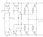
Here is a schematic... ....the feedback is not shown, one inverting input stage is also missing.
-Dan
halojoy said:
How do you measure the noise?
It is with no input signal?
How is distortion with sinus signal?
Is it changing with the supply voltage, as well?
/halo - the homemade expert on noise
Bias for AB output devices is directly across several diodes. One Zener, and 3 standard diodes. My output devices are mosfet, so voltage needs to be around 6 yo 7 volts or so. Across the diodes, any changes in the bias current has very very little effect on bias voltages. This voltage remains constant even up to 100Khz, at 50W output.
As for the noise, I measure it with my scope. It automatically calculates the RMS of waveforms (And many other measurements). I measure with no input signal, and an 8 ohm load. Absoutley nothing changes except the rail voltages. (I turn the knob on a variac to adjust voltages)
I see no distortion on a sine or triangle waveforms through the entire input voltage range (+- 10 Volts to +-80 volts). I also checked the drive signal to the AB output stange. This is also a very nice clean sine (or triangle) waveform.
Typically, I will see crossover distortion here, when the bias voltage between output devices is too small and the differential pair is compensating.
Now, you have me thinking, I wonder if the zener generates more noise with less bias current? Interesting. But, this seems a little excessive, since the gain of the output stage is 1. The zener would need to make 12mV RMS... ...not sure, but it seems a little much.
I'm going to have to start digging around for sources of noise. The amp is fairly high gain (40dB), so any input noise will be amplified greatly.
Here is a schematic... ....the feedback is not shown, one inverting input stage is also missing.
-Dan
Attachments
Re: Re: Re: Weird, Less noise with more voltage.
I NEVER use Zeners in my audio circuits.
It is well known that they are "noisy".
compared to smallsignal diodes, LEDs and small signal transistors.
There are several better ways to generate constant voltage.
The most used is the common amplified diode
configured low noise transistor.
Sometimes you can improve this amplified diode
by using two transistors. A two stage amplifier.
Especially when the current through the stage changes a lot
from idle value, when the amplifier works with signals.
This is mostly not the case
when MOSFETs are used in the output stage.
I find no need to use zeners, ever. In audio circuits.
I do not understand why this is done?
Maybe you are right, the noise can change to lower,
at a higher current in the zener.
Maybe some reminiscent from "the old days".
/halojoy
Yes, it might be the only. The zener.dkemppai said:
Bias for AB output devices is directly across several diodes. One Zener, and 3 standard diodes. My output devices are mosfet, so voltage needs to be around 6 yo 7 volts or so. Across the diodes, any changes in the bias current has very very little effect on bias voltages. This voltage remains constant even up to 100Khz, at 50W output.
Now, you have me thinking, I wonder if the zener generates more noise with less bias current? Interesting. But, this seems a little excessive, since the gain of the output stage is 1. The zener would need to make 12mV RMS... ...not sure, but it seems a little much.
-Dan
I NEVER use Zeners in my audio circuits.
It is well known that they are "noisy".
compared to smallsignal diodes, LEDs and small signal transistors.
There are several better ways to generate constant voltage.
The most used is the common amplified diode
configured low noise transistor.
Sometimes you can improve this amplified diode
by using two transistors. A two stage amplifier.
Especially when the current through the stage changes a lot
from idle value, when the amplifier works with signals.
This is mostly not the case
when MOSFETs are used in the output stage.
I find no need to use zeners, ever. In audio circuits.
I do not understand why this is done?
Maybe you are right, the noise can change to lower,
at a higher current in the zener.
Maybe some reminiscent from "the old days".
/halojoy
Re: Re: Re: Re: Weird, Less noise with more voltage.
I am planning on switching to an amplified diode. The amp is still a pile of wires pushed into a breadboard, and glued onto a heatsink. The amplified diode can also help to give me some thermal stability. I've plotted some them compensation curves for these fets, and will fit the amplified diode to match them. But, I'm not to the point of worrying about that just yet.
Still, I think that ther noise from the zener would only affect bias current, and not the actual output voltage. The noise spectrum shows it's flat from DC on up. I would suspect that the amplifier would respond to low frequency noise in this stage, and try to cancel it. (Maybe not???) I'm thinking that the noise comes from one of the more foreword stages.
The noise is low enough that I cannot hear it until my ear is two inches from the speaker. Even so, really need a good spectrum analyzer, and THD measurement equipment!
-Dan
halojoy said:
There are several better ways to generate constant voltage.
The most used is the common amplified diode
configured low noise transistor.
Sometimes you can improve this amplified diode
by using two transistors. A two stage amplifier.
Especially when the current through the stage changes a lot
from idle value, when the amplifier works with signals.
/halojoy
I am planning on switching to an amplified diode. The amp is still a pile of wires pushed into a breadboard, and glued onto a heatsink. The amplified diode can also help to give me some thermal stability. I've plotted some them compensation curves for these fets, and will fit the amplified diode to match them. But, I'm not to the point of worrying about that just yet.
Still, I think that ther noise from the zener would only affect bias current, and not the actual output voltage. The noise spectrum shows it's flat from DC on up. I would suspect that the amplifier would respond to low frequency noise in this stage, and try to cancel it. (Maybe not???) I'm thinking that the noise comes from one of the more foreword stages.
The noise is low enough that I cannot hear it until my ear is two inches from the speaker. Even so, really need a good spectrum analyzer, and THD measurement equipment!
-Dan
You have a cap across the bias circuit, so it's not going to
be the zener unless the cap is small, and even then it's
common mode, so it's still unlikely.
When you can't find the obvious cause for noise that is
supply value related, then it is often oscillation, although
most often the circuit will oscillate when the supply increases.
be the zener unless the cap is small, and even then it's
common mode, so it's still unlikely.
When you can't find the obvious cause for noise that is
supply value related, then it is often oscillation, although
most often the circuit will oscillate when the supply increases.
No contribution to this is that the current generator to the emitter follower (middle, at the top) seem to be a small degree of weird?
You don't have a stable current throught the second high-gain stage. Your idea of "compound transistors" aren't so well tested.
If you have a constant base current to a single transistor you will get a very sensistive stage for voltage variations. You must secure stable operating currents with varying voltage. The power supply rejection (PSSR) for one thing will be low, not good for distortion. Using cascodes is an easy way to create high immunity against varying voltage
The resistor//diode thing is a typical thinking of "large signal" when you should think "small signal". The perpose of the resistor is to insert losses to the resonance circuit (in order to the oscillation). Paralleling a diode is the same as paralleling with a cap, rather good one too. Normal standard is resitor, resistor+ ferrite bead or ferrite bead alone.
Attachments
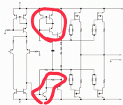
peranders said:No contribution to this is that the current generator to the emitter follower (middle, at the top) seem to be a small degree of weird?
peranders,
The circuit in the top circle is a brute force current source using some small signal transistors, and one larger higher power device. The Current is set by beta of the particular output transistor (which can change), and the current from current mirror. (I use that particualr current mirror, because I etched a dozen boards, with leads that plug into my breadboard.)
I'm still thinking of improvements for that particular stage, however, I don't think that it'll be cascode.
As for the bottom circuit, the resistor is there to increse slew rate. The complementary pair if fairly slow otherwise, and a diode may be unable to pull the voltage low enough. (Resistor and capacitor selected to the minimum value needed for stability.
Keep in mind that this amplifier is really designed for high power, and trying to do so with simplicity in mind. Output powers of around 200 to 300 Watts @ 8 ohms are the target.
-Dan
peranders said:No contribution to this is that the current
I ment "My contribution", not "No".....
peranders said:Maybe your idea is something but I think stable operating points are essential in order to get predictable results. I if you can't get each stage working without feedback, it's not a good sign.
peranders,
The design is stable, infact, it's very stable. Good frequency, and phase response. From DC to well over 100Khz at all signal levels.
I've been listening to it for a few days now, And have no problems whatsoever with it.
However, it still remains to be explained why the noise levels fall when the rail voltage is increased. (Again, I must stress that the noise levels are seen on the scope, and I cannot hear the above ambient noise in the house.)
Circlotron,
Higher gain is a possibility. I have notied that the the rising edge slew rate increases with higher voltage levels. So what you have suggested is definatley possible.
I've though about this also. I will probably try some testing at higher bias levels tonight. I'll try some tests with the same bias currents at higher and lower voltages.
Nelson,
It's not an oscillation, at least not one that I can find with the scope (And FFT on scope). Normally, I would think that the Brownian/Johnson noise would increase with the increased bias levels (Because of the increase in the temperature of the active devices). Maybe I'm wrong about this, but usually hotter devices generate more noise (In theory anyway).
I think that Circlotron may be onto something.
-Dan
Still Weird!
Ok, I did some spectrial measurements, and the there are no frequency peaks (Except for a 13Khz signal, which dissappears when I shut my monitor off). I mean none, not even up to 300+ mhz.
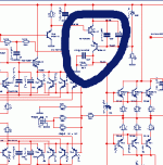
I lowered the rail voltage to +-20Volts, and noted around 20mV RMS noise. I then doubled the bias current into the first stage shown on the schematic, and noted an increase in noise. To around 22mV, I reduced the bias (to half), and noted a reduction in noise to around 18mV. more bias current = more noise. (Which makes sense, since more bias = more heat, more noise...)
On with the test! I tried increasing the bias currents into the second stage shown on the schematic, Same thing, more noise with more bias, and less noise with less bias.
Returning the bias to "normal" levels, I increased the rail voltages and noted a reduction in noise to around 9mV. Very weird, as the increase in rail voltage also increased the bias currents by a factor of 2.
I tried changing the bias current on the first stage at higher levels of voltage, only to find that it pretty much doesn't matter. Weird, weird, weird.
Circlotron,
Also, I tried adding some more 'Miller' capacitance to the grounded emitter stage (//Cap in series with the resistor on grounded emitter). Thus, to reduce open loop gain. Doing so reduced the noise voltage by a factor of 2! (To about 5.5mV) It seems this is counterintuitive to your idea.
This cap, However will not stay there, since it actually dulls the sound a small but noticable ammount. (Changed from 5 to 47pF) I probably would not notice the difference, except that I was able to push it in and out of the circuit, and the high frequencies lost their clarity, again only a very very slight ammount. I may measure the difference in gain/phase later, but seem to remember that this only affected phase not gain. (Phase maybe -2 or -3 degrees at 20Khz)
-Dan
P.S. (I'm listening to a song recorded live, It's just amazing, just amazing.)
Ok, I did some spectrial measurements, and the there are no frequency peaks (Except for a 13Khz signal, which dissappears when I shut my monitor off). I mean none, not even up to 300+ mhz.
I lowered the rail voltage to +-20Volts, and noted around 20mV RMS noise. I then doubled the bias current into the first stage shown on the schematic, and noted an increase in noise. To around 22mV, I reduced the bias (to half), and noted a reduction in noise to around 18mV. more bias current = more noise. (Which makes sense, since more bias = more heat, more noise...)
On with the test! I tried increasing the bias currents into the second stage shown on the schematic, Same thing, more noise with more bias, and less noise with less bias.
Returning the bias to "normal" levels, I increased the rail voltages and noted a reduction in noise to around 9mV. Very weird, as the increase in rail voltage also increased the bias currents by a factor of 2.
I tried changing the bias current on the first stage at higher levels of voltage, only to find that it pretty much doesn't matter. Weird, weird, weird.
Circlotron,
Also, I tried adding some more 'Miller' capacitance to the grounded emitter stage (//Cap in series with the resistor on grounded emitter). Thus, to reduce open loop gain. Doing so reduced the noise voltage by a factor of 2! (To about 5.5mV) It seems this is counterintuitive to your idea.
This cap, However will not stay there, since it actually dulls the sound a small but noticable ammount. (Changed from 5 to 47pF) I probably would not notice the difference, except that I was able to push it in and out of the circuit, and the high frequencies lost their clarity, again only a very very slight ammount. I may measure the difference in gain/phase later, but seem to remember that this only affected phase not gain. (Phase maybe -2 or -3 degrees at 20Khz)
-Dan
P.S. (I'm listening to a song recorded live, It's just amazing, just amazing.)
The saga continues...
peranders,
Could you go into depth a little about why you think that the PSRR would suffer because of the topology involved. Sorry, but I seem to have missed something in your other posts.
A finally did a little PSRR testing of the amplifier. Here are what I've found. (I have some imporvements to make, but have just not had time)
+- Rails (V) PSRR (dB)
20 42
35 50
50 64
60 67
(Note, My plan is to run at about +- 85 volts.)
I don't recall ever seeing a graph of PSRR vs supply rail for any amp, but would suspect an increase in PSRR with increasing rail voltage.
Anyone, Comments???
-Dan
Increasing bias current may REDUCE noise.
I'm currently designing a preamp comprising a J-FET differntial amp. at the input. It's is clear from the datashett regarding the 2SK170 that the equivalent input noise is reduced if the drain current is increased.
The noise conveges at approx 3 mA.
This is a implication from the fact that the forward transfer conductance increases with drain current.
Morello said:Increasing bias current may REDUCE noise.
This is what I thought too. But after actually trying the amp at different levels of bias, I have found that no matter what voltage I'm at, more bias increases the noise. But again, I'm using BJT's at the input. I need to do some review of the transconductance model of BJT's... ...might make sense.
I'm still confused by the increase in voltage reducing the noise. It just goes agains everything I thought I knew. (Tells you how much I really knew, now doesn't it?
) I've got to be missing something.-Dan
Any resultdkemppai said:
This is what I thought too. But after actually trying the amp at different levels of bias, I have found that no matter what voltage I'm at, more bias increases the noise. But again, I'm using BJT's at the input. I need to do some review of the transconductance model of BJT's... ...might make sense.
I'm still confused by the increase in voltage reducing the noise. It just goes agains everything I thought I knew. (Tells you how much I really knew, now doesn't it?
-Dan
to why this occurs ....
New ideas?
/halo
- Status
- This old topic is closed. If you want to reopen this topic, contact a moderator using the "Report Post" button.
- Home
- Amplifiers
- Solid State
- Weird, Less noise with more voltage.