Hi,
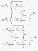
I'm planning to do some upgrade for my AB Class amplifier. How I should use charge suck out capacitors after or before base stoppers? I attached the images of possible variants. My output stage looks the same Rb1=Rb2=10 ohm R=100 ohm. But output uses three paralled output trasistor pairs.
Where I shoud use charge suckout capacitor? And which value should I chose? It is better to use one bigger value capacitor or three smaller ones?
My output devices are toshiba's 2SC5200/2SA1943
Attachments
Hi Mindaugas
I may say only some of your idea .
I think the better circuit of the Ccs is under fig .
The cap warks ‚’eduction of impedance.
The one of upper fig , it decrease frequency characteristic of Amp.�@
A�@Reference�@circuit of the cap that to use same purpose is follow
C11 of P.3 of
http://easy-audio-kit2.hp.infoseek.co.jp/DACManual/Amp_v2.pdf
The parent directory is
http://easy-audio-kit.hp.infoseek.co.jp/
This is a page of the kit which an amateur distributes,electoric Vol,power amp,DAC,etc
sorry it is only in Japanese
Only second fig is valid. In first fig using Rb1 and Rb2 doesn't make much sense. These are usually small (about 5Ohm), and are here for lovering quality of parasitic resonance circuits formed by wiring iductance and internal transistor capacitance. On first figyou are yust closing that parasitic circuit, and then make high risk of oscilations. (sory for my very bad english)
- Status
- This old topic is closed. If you want to reopen this topic, contact a moderator using the "Report Post" button.