we could start an new terminology debate here - I don't consider the Leach Super amp output to be a "true cascode" - rather a cascade/totem pole that equally splits the dynamic Vdrop - for better utilization of SOA with devices having second breakdown
I would reserve the term "cascode" for the case when one device holds the other's Vcb nearly constant
I would reserve the term "cascode" for the case when one device holds the other's Vcb nearly constant
Originally Posted by Bob Cordell
VTS = Very Tough Sell.
Well, i like it
") & it fits the bill. Ohh that word BILL has more than 1 meaning
& it fits the bill. Ohh that word BILL has more than 1 meaning I think the IRs acronym should be changed to FTC (F_ing Tax Collector).
There ya go !
Oops, that is already taken
Taken is quite appropriate too
@ Damon Hill
Hi, even though you've been diagnosed with ADD, plus you say that you're a slow learner, it hasn't prevented you with Wanting to learn more, & indeed Actually doing so
I myself am far from being an expert, & don't understand a lot, & make mistakes, but i try to learn from them, & don't allow Anything/Anybody to impeed my progress, nor should you, or Anybody else. All the best for the future It depends.....
Hi Bob,
Yes and No.
It depends whether we consider the resistive LTP load being a part of the input stage (case 1) or being a part of the 'intermediate' stage (case 2).
In case 1, it is voltage in and voltage out, thus the 'intermediate' stage is a VAS.
In case 2, it is current in and voltage out, thus the 'intermediate' stage is a TIS.
Cheers,
E.
Hi Edmond,
[..]
Consider an amplifier that uses a resistively-loaded LTP input stage followed by a VAS with a preceding emitter follower (what I sloppily refer to out of convenience as a Darlington VAS). Consider that amplifier does not use Miller compensation, but rather lag compensation at the collector of the VAS. That VAS is certainly not a transimpedance stage.
[..]
Cheers,
Bob
Hi Bob,
Yes and No.
It depends whether we consider the resistive LTP load being a part of the input stage (case 1) or being a part of the 'intermediate' stage (case 2).
In case 1, it is voltage in and voltage out, thus the 'intermediate' stage is a VAS.
In case 2, it is current in and voltage out, thus the 'intermediate' stage is a TIS.
Cheers,
E.
It depends whether we consider the resistive LTP load being a part of the input stage (case 1) or being a part of the 'intermediate' stage (case 2).
By the same "logic" the "intermediate stage" can also be considered as a current amplifier, or even a transconductance amplifier. So it can be a VAS, TIS, TCS, or CAS. As this would cover all cases, may I suggest WAS (Whatever Amplifier Stage).
we could start an new terminology debate here - I don't consider the Leach Super amp output to be a "true cascode" - rather a cascade/totem pole that equally splits the dynamic Vdrop - for better utilization of SOA with devices having second breakdown
I would reserve the term "cascode" for the case when one device holds the other's Vcb nearly constant
I agree completely.
Cheers,
Bob
Okay, I'm a slow learner. Maybe it has to do with my recently diagnosed attention deficit disorder, but it sure took a long time to soak into my thick skull. I do have an awful hard time with the learning process, and studying abstract subjects like electronics.
I'm finally cluing in on cascoded amplifiers, and somewhat on how they greatly improve on a transistor's inherently non-linear behavior (but not completely, of course on Class B non-linearity at cutoff), before negative feedback is applied. For all the decades of building and enjoying Marshall Leach's amplifier, I'd ignored his 'Super Amplifier' and its rather different Version 2 iteration simply because I was just looking at it as a much higher powered amplifier I didn't think I needed.
Between Bob's book, Leach's amplifiers that employ cascoding to one degree or another, and Nelson Pass's designs, it's sunk in like a firmly applied baseball bat to my noggin. I'm surprised the practice isn't much more pervasive.
Of course, there's quite an increase in transistor parts count if cascoding is fully applied--those Krell and Pass amplifiers are >expensive<. But I coulda had a Leach Superamp by now if I'd only thought it through back in the 80s or 90s.
Forget error correction design for the moment. Any suggested reading on the subject of cascoding? I've been struggling for a long time on how to go beyond Leach's Low TIM "little" amplifier but never stumbled onto a newer design that really appealed to me, even though error correction seemed to have possibilities. Leach's amplifier worked a little >too< well, alas.
I'm going back to basics, the heart of a transistor's non-linearity. Maybe there's a downside I've not discovered about cascoding, but that's part of the learning curve, too. Time to rethink.
(For the moment and because of outright poverty, I'm having to settle for applying Thermaltrak transistors to my prototyping chassis and seeing how these faster and more linear perforated emitter devices sound and measure.)
Hi Damon,
Lots of engineers and some well-known gifted people have ADD. My son has ADD and that is how I discovered that I have it - it is often passed on through the male side. The term can be a misnomer. It does NOT mean that a person cannot focus intensely on a particular thing for an extened period when one has a reason to do so.
Cascoding can help a lot with the Early effect nonlinearity in transistors, and with the effects of nonlinear Ccb feedback capacitance, but how much cascoding brings to the table is quite dependent on the individual circuit. Cascoding is often not expensive in terms of a couple of added 10-cent transistors, if you are talking about small-signal cascode circuits. However, sometimes cascoding can carry with it a reduction in HF stability that must be watched out for in the design and layout process.
Cheers,
Bob
we could start an new terminology debate here - I don't consider the Leach Super amp output to be a "true cascode" - rather a cascade/totem pole that equally splits the dynamic Vdrop - for better utilization of SOA with devices having second breakdown
I would reserve the term "cascode" for the case when one device holds the other's Vcb nearly constant
I'm looking at the version 2.1 schematic, which is significantly different from the original version published in Audio. But I think I see what you mean; a voltage divider from rail to output establishes a 50% level from VAS to drivers to output 'top' transistors. The difference in version 2.x is that there are cascades(?) for each transistor rather than version 1 which really looks more like a voltage regulator to me, with all of the lower level transistors' collectors tied together.
http://users.ece.gatech.edu/mleach/superamp/circuit.pdf
In retrospect, because I hadn't been aware of the difference in designs, I ended up rather confused when I was comparing them to the Heathkit AA-1800 (and Dan Meyer's Tigersaurus uses CFP in totem pole--I built one very long ago and it seemed to work well). I'm still trying to understand the differences in Leach's implementations.
Oh well...time to haul out the curve tracer and the bench supplies, and do some basic circuits. Trying to find past threads on diyAudio that cover this subject; I know they're buried out there somewhere.
And this looks like a good one:
http://www.diyaudio.com/forums/solid-state/117225-cascode-output-stages.html
ADD has been a tremendous problem for me over the years, and I just have to muddle through as best I can.
Last edited:
I have ADD, too. But I think of it as "AGILE FOCUS".
Some of you might also want to take the on-line test for Asperger's Syndrome, which seems to be fairly common in engineer/scientist types.
And for ADD, if your doctor hasn't had you try generic time-released dextroamphetamine, you might be suffering more than necessary.
Some of you might also want to take the on-line test for Asperger's Syndrome, which seems to be fairly common in engineer/scientist types.
And for ADD, if your doctor hasn't had you try generic time-released dextroamphetamine, you might be suffering more than necessary.
Last edited:
Coming in very, very late, I just wondered whether Edmond has finished his amp to compare it against the Cordell solution.
Reason to post is that the circuit used by Edmond IMO is far superior from a practical point of view, because there is no need for any trimming and because of no thermal sensitivity.
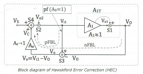
Bob Cordell used Hawksford Error Correction (HEC) as a solution to reduce THD, while Edmond Stuart used Active Error Feedback (AEF).
See the first figures below for the difference between the two.
For the HEC version you have to meticulously tune low tempco resistors to get exactly a compound gain of 0dB for the circuitry around Amplifier A1, but result can be quite good.
THD distortion reduction drops very rapidly when not tuning very secure, not the easiest thing to do.
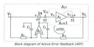
An AEF on the other hand needs no tuning at all and relies on high gain stage, in the figure below represented by amp A2.
Only the BW of A2 has to be taken care of, to prevent a bulge at the high end of the FR.
In Edmonds circuit diagram this was t3=R3*C1
And also t2=R2*C2 should roughly be equal to t1=R1*C1, where C2 in the effective input capacity of the Mosfet and R2 the gate resistor.
But this is not critical, a match of 10% is more than enough.
When inserting a pot between the junction of R3 and R13 and Out, the bulge could be trimmed depending on the gain of the output transistors, but this is also not critical at all.
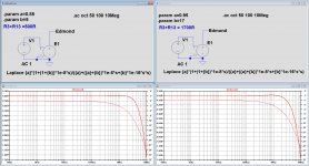
See the sim below for a gain of 0.85, where 500R should be used for R3 and for a gain of 0.95 where 1k7 should be used to get a bulge-less FR.
But in case of 0.95 gain and 500R, the bulge at 4Mhz is still below 1dB, that's how low the sensitivity is.
Without any trimming at all, results in the audio range should be fully comparable to an optimally tuned HEC.
Hans
Reason to post is that the circuit used by Edmond IMO is far superior from a practical point of view, because there is no need for any trimming and because of no thermal sensitivity.
Bob Cordell used Hawksford Error Correction (HEC) as a solution to reduce THD, while Edmond Stuart used Active Error Feedback (AEF).
See the first figures below for the difference between the two.
For the HEC version you have to meticulously tune low tempco resistors to get exactly a compound gain of 0dB for the circuitry around Amplifier A1, but result can be quite good.
THD distortion reduction drops very rapidly when not tuning very secure, not the easiest thing to do.
An AEF on the other hand needs no tuning at all and relies on high gain stage, in the figure below represented by amp A2.
Only the BW of A2 has to be taken care of, to prevent a bulge at the high end of the FR.
In Edmonds circuit diagram this was t3=R3*C1
And also t2=R2*C2 should roughly be equal to t1=R1*C1, where C2 in the effective input capacity of the Mosfet and R2 the gate resistor.
But this is not critical, a match of 10% is more than enough.
When inserting a pot between the junction of R3 and R13 and Out, the bulge could be trimmed depending on the gain of the output transistors, but this is also not critical at all.
See the sim below for a gain of 0.85, where 500R should be used for R3 and for a gain of 0.95 where 1k7 should be used to get a bulge-less FR.
But in case of 0.95 gain and 500R, the bulge at 4Mhz is still below 1dB, that's how low the sensitivity is.
Without any trimming at all, results in the audio range should be fully comparable to an optimally tuned HEC.
Hans
Attachments
Last edited:
Hi Hans,
This is a very good question, and I wish Edmond was still on DIYaudio. I don't recall much of the detail that distinguished Edmond's AAF, but the diagram you posted looks pretty much like the technique that has been around for a very long time, where it turns out that extra conventional NFB loop gain is put around the output stage. Interestingly, if one analyzes HEC in a particular way, it also just adds more NFB around the output stage, just in a somewhat different way.
For all such schemes, it comes down to implementation in the real world and stability. I don't recall if Edmond actually built and measured his amplifier.
It is also important to realize that for situations where the distortion of a power amplifier is 0.001% and under, simulations become less accurate in predicting distortion, due to imperfect transistor models and the absence of many parasitic elements in a real implementation.
One thing that many people do not understand about HEC and the way I implemented it is that it really does not need trimming to realize most of its effectiveness in the real world. It is nice to have the trimmer ability, but in most cases that setting will be found in development and the trimmer replaced with a 1% resistor.
If you have not, I urge you to read my JAES paper, "A MOSFET Power Amplifier with Error Correction", a PDF of which is available on my web site at cordellaudio.com.
Cheers,
Bob
Hi Bob,
What a nice surprise hearing from you.
I don't want to go in the sort of hectic discussions as seen in this thread, but I have two reactions:
1) Hec MUST by definition have a gain of 1.
The fact that your amp works fine with 1% resistors is most likely because you did all the work in advance to find out the perfect values, but I remember a posting from Syn08 who had to use different values for optimal results, possibly because he used different trannies. With AEF this will have no impact.
2) Simulations are as reliable as the models of the used components as you are well aware of.
But building various amps, sim and build always came remarkably close in my case, as long as THD is above -120dB.
It is easy to simulate a 0.01ppm Amp but almost wishful thinking to realise.
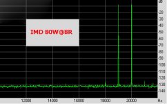
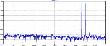
As an example I show an IMD Measurement at the left and Sim at the right of my 100W@8R Main Amp, equipped with AEF, both images at 80W@8R.
White noise was added in the LTSpice Sim simulating the input noise to get a result as close to reality as possible.
Remarkably close, true ?
Hans
What a nice surprise hearing from you.
I don't want to go in the sort of hectic discussions as seen in this thread, but I have two reactions:
1) Hec MUST by definition have a gain of 1.
The fact that your amp works fine with 1% resistors is most likely because you did all the work in advance to find out the perfect values, but I remember a posting from Syn08 who had to use different values for optimal results, possibly because he used different trannies. With AEF this will have no impact.
2) Simulations are as reliable as the models of the used components as you are well aware of.
But building various amps, sim and build always came remarkably close in my case, as long as THD is above -120dB.
It is easy to simulate a 0.01ppm Amp but almost wishful thinking to realise.
As an example I show an IMD Measurement at the left and Sim at the right of my 100W@8R Main Amp, equipped with AEF, both images at 80W@8R.
White noise was added in the LTSpice Sim simulating the input noise to get a result as close to reality as possible.
Remarkably close, true ?
Hans
Attachments
the diagram you posted looks pretty much like the technique that has been around for a very long time, where it turns out that extra conventional NFB loop gain is put around the output stage. Interestingly, if one analyzes HEC in a particular way, it also just adds more NFB around the output stage, just in a somewhat different way.
Bob
I fully agree Bob. In the end, it relies on the open loop gain being ideally infinite, and the improvement limit corresponds to the open loop attainable.
HEC has the additional handicap that the correction element needs to have a very accurate gain, which is the ultimate limit to the correction that can be attained. Plus that the correction element needs a bandwidth (much) larger than the correction bandwidth. Been there, done it, got a patent, been laughed at ;-)
Jan
Hi ! Nice to meet again Bob, Jan !! Well over 10 years later !
Yes, after some dedication to the error correction concept, I fell to the conclusion it is an extreme form of negative feedback where essentially you have an inner node with infinite gain attained through unity gain positive feedback loop. This infinite gain in the global feedback loop makes for ideal correction.
While this infinite gain stage may sound shocking at first, it does not necessarily imply instability. One must be reminded there is no practical active device whith infinite bandwith, it can be shown a band limited summing node with unity gain positive feedback degenerates to an ideal integrator which is merrily stable despite infinite DC gain (it ramps up or down at a finite rate).
I did build several amplifiers - and have my own amplifiers made this way - and stability can be tamed in straightforward ways.
I use multiturn trimpots for inner loop gain tuning, this is not realy a necessitiy but I find rewarding - I remember Bob saying likewise - to "tune out distortion" in real time looking at the output spectrum.
As to whether this technology brings a game changing step in performance, honestly and after a good effort put in it I do not think so in the end.
Yet some insights I got while at this I found relevant, particularily the importance of the highest possible bandwith in the lower level stages as the foundation for good performance in high global feedback topologies.
Cheers !!
Yes, the bandwidth requirement for the correction element is straight forward. At the time (more than a decade ago) I actually calculated all this.
Example: if you want to lower your no-correction distortion by 40dB, the correction element accuracy needs to be better than 1% (this is also intuitively but I could prove it).
Secondly, if you want this correction to be effective up to frequency F, the bandwidth of the correction element needs to be at least 100*F. A bit less intuitive, but somewhat.
Jan
I fully agree Bob. In the end, it relies on the open loop gain being ideally infinite, and the improvement limit corresponds to the open loop attainable.
HEC has the additional handicap that the correction element needs to have a very accurate gain, which is the ultimate limit to the correction that can be attained. Plus that the correction element needs a bandwidth (much) larger than the correction bandwidth. Been there, done it, got a patent, been laughed at ;-)
Jan
Hi Jan,
Small correction, with Hec the loop gain is only 1. That you don’t need gain is the beauty of it, but with Aef loop gain is very large. Look at the two images in my previous posting.
That’s why Hec needs meticulous trimming to get 0dB, but with Aef no trimming is needed at all.
Hans
Hi ! Nice to meet again Bob, Jan !! Well over 10 years later !
Yes, after some dedication to the error correction concept, I fell to the conclusion it is an extreme form of negative feedback where essentially you have an inner node with infinite gain attained through unity gain positive feedback loop. This infinite gain in the global feedback loop makes for ideal correction.
While this infinite gain stage may sound shocking at first, it does not necessarily imply instability. One must be reminded there is no practical active device whith infinite bandwith, it can be shown a band limited summing node with unity gain positive feedback degenerates to an ideal integrator which is merrily stable despite infinite DC gain (it ramps up or down at a finite rate).
I did build several amplifiers - and have my own amplifiers made this way - and stability can be tamed in straightforward ways.
I use multiturn trimpots for inner loop gain tuning, this is not realy a necessitiy but I find rewarding - I remember Bob saying likewise - to "tune out distortion" in real time looking at the output spectrum.
As to whether this technology brings a game changing step in performance, honestly and after a good effort put in it I do not think so in the end.
Yet some insights I got while at this I found relevant, particularily the importance of the highest possible bandwith in the lower level stages as the foundation for good performance in high global feedback topologies.
Cheers !!
Yes, you have largely hit the nail on the head. Understanding that there is effectively a unity gain positive feedback loop within the negative feedback loop is key. There are some things about the HEC toplogy that seem to mitigate some difficulties in the real world. One thing that is interesting in my implementation is that the compensation needed for the HEC (yes, since it involves NFB it needs compensation) is that the primary compensation for the HEC loop acts in a sort of feedforward way to the global loop. The simplicity of the circuit is quite remarkable. Only the two HEC transistors are not emitter followers.
The circuit I used could be improved upon. For example, the HEC transistors could be made CFPs to reduce the distortion they contribute because of their signal-dependent dynamic emitter resistance. Another point worth noting is that MOSFETs need HEC and HEC loves MODFETs. The high speed of the vertical MOSFETs, with equivalent ft well above 100 MHz, allows significant speed in the HEC loop.
The amplifier I did came in at about 0.0006% THD+N at 20 kHz in a 200 kHz measurement bandwidth at full power of 50W, using only a single pair of MOSFETs biased at about 150 mA. The pot was not hard to adjust at all, and it was fun to watch the distortion residual become inverted as the pot went past the optimum.
Without HEC, THD-20 was 0.02%. With HEC, THD-20 was 0.0006%, for a total effectiveness of 33:1, or about 30 dB. At 20 kHz, I'll take a 30-dB distortion reduction any day of the week. The open-loop output stage distortion saw a similar reduction, from a 2.5% p-p residual down to a 0.1% residual. Open-loop output stage distortion means distortion measured at the output when the global amplifier feedback loop is closed before the output stage.
It is also notable that some of that 0.0006% distortion was attributable to the IPS-VAS. That amplifier used an ordinary differential cascode on the input differential pair, with the cascode bases connected to a fixed bias. At a later point in time, I experimented with a driven cascode, where the cascode bases are driven with a replica of the feedback signal, and saw some distortion reduction.
Cheers,
Bob
Hi Jan,
Small correction, with Hec the loop gain is only 1. That you don’t need gain is the beauty of it, but with Aef loop gain is very large. Look at the two images in my previous posting.
That’s why Hec needs meticulous trimming to get 0dB, but with Aef no trimming is needed at all.
Hans
I would definitely not use the word "meticulous" to describe the trimming.
In fact, as I mentioned earlier, once the correct value is found from trimming, one still achieves great results without the trim as long as the design still uses the same circuit and components. The 30:1 reduction I got suggests that one only needs to get within about 3% anyway.
The trim is trivial to do as long as you have equipment good enough to see the low distortion that results. Back in 1983, it was quite a challenge for me to see 0.0006% THD+N in a 200 kHz measurement bandwidth. I would love to have had a spectrum analyzer that could go to 200 kHz with good dynamic range back then. I used the essence of the Distortion Magnifier back then to do the measurements.
Cheers,
Bob
Hi Bob,
What a nice surprise hearing from you.
I don't want to go in the sort of hectic discussions as seen in this thread, but I have two reactions:
1) Hec MUST by definition have a gain of 1.
The fact that your amp works fine with 1% resistors is most likely because you did all the work in advance to find out the perfect values, but I remember a posting from Syn08 who had to use different values for optimal results, possibly because he used different trannies. With AEF this will have no impact.
2) Simulations are as reliable as the models of the used components as you are well aware of.
But building various amps, sim and build always came remarkably close in my case, as long as THD is above -120dB.
It is easy to simulate a 0.01ppm Amp but almost wishful thinking to realise.
As an example I show an IMD Measurement at the left and Sim at the right of my 100W@8R Main Amp, equipped with AEF, both images at 80W@8R.
White noise was added in the LTSpice Sim simulating the input noise to get a result as close to reality as possible.
Remarkably close, true ?
Hans
Excellent work, Hans!
- Home
- Amplifiers
- Solid State
- Bob Cordell Interview: Error Correction