Nixie said:If you leave the primaries alone there's no problem here.
Fortunately the better toroid manufacturers put the primary
windings on first, and give them a good isolation wrap.

If, however, error in the output stage causes the magnitude of its output to be less than that at its input, the major loop provides positive rather than negative feedback, as alluded to here.
This, incidentally, is virtually the norm with practical complementary emitter/source followers, given that they deliver a voltage gain of slightly less than unity.
Running AC-analysis as previously described, now reveals a marked deterioration with respect to the resonant peak in the loop-gain response.
This is why EC circuitry require that the minor loop be progressively attenuated at ultrasonic frequencies if stability is to be maintained.
Note that loop transmission at LF is again equal in magnitude (0.2) to the error generated by the output stage, as expected.
Attachments
The stabilized loop (courtesy of C1 & C2) now eliminates the resonance, ensuring that loop transmission remains less than unity (viz. roughly equal to the error (1-0.8=0.2) generated by the output stage) to maintain stability.
This is consistent with the less-than-unity loop gains obtained with Cordell's embodiment of Hawksford's circuit.
This is consistent with the less-than-unity loop gains obtained with Cordell's embodiment of Hawksford's circuit.
Attachments
andy_c said:In Hawksford's equations for the component values of his error correction circuit, he neglected the effect of the error correction transistor re.
One possible thing to try might be replacing the error correction transistors by CFPs.
Hi Andy,
I missed this post somehow.
Indeed, re does have a non-negligible impact on Hawksford's arrangement in practice
Thanks for the insight; an excellent idea!
mikeks said:Indeed, re does have a non-negligible impact on Hawksford's arrangement in practice
Hi Mike,
One tool that helped me in simulation to understand what effect (if any) the diff amp had on the residual distortion was this fake diff amp that I posted earlier in the thread. Un-grounding the plus input of G1 and the minus input of G2 gives a semi-idealized diff amp. This has a constant gm until it hits a hard current limit of I0 (via the "table" directive). So you can specify gm and I0, and the collector resistor adjusts for unity gain. There's a DC bias current that will set up a DC voltage drop across the collector resistor the same as an actual diff amp. So you can play around in sim with the idealized diff amp, then replace it with the model of the real one and see if the residual distortion increases. If it does, then you can play around with the actual diff amp model to improve things.
Just a little side note: it occurs to me that any number of differential amplifier ICs (like the INA134) would be trivially easy to use for error correction. Performance would be pretty good without trimming because of the precise ratiometric resistor matching available in ICs.
Bob Cordell said:In general, I always say that if you are going to the trouble of making a very good amplifier, then you should always spend the small extra cost on a boosted-rail power supply for the input and driver stages.
The second approach is to just use a small additional 10-15 VA small transformer with two isolated secondaries.
Mr Cordell,
any more of this and i'll be hanging your poster on my wall, kneel down on a carpet three times a day and bend my head towards New Jersey.
Allow me to add that it's also a cheapo for an Ebenezer DIY ampliholic.
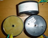
Dropping the output voltage of a small voltage booster transformer to the desired raised voltage level is easy.
I used to buy fancy new block type transformers to serve time as voltage boosters for the front end of both BJT and MOSFET amps.
Nowadays i buy stuff like NOS resin filled telephone transformers for $0.50-$1 the piece to do the job.
Thank you for also mentioning the driver stages, i've been trying to get that message across on some of the amplifier threads here but i'm a lousy preacher.
Hail to the Messiah.
Attachments
Tim__x said:Just a little side note: it occurs to me that any number of differential amplifier ICs (like the INA134) would be trivially easy to use for error correction. Performance would be pretty good without trimming because of the precise ratiometric resistor matching available in ICs.
Yes, but diff. amps. S1 and S2 here would have to accommodate half the output voltage swing at each of their inputs while rejecting the necessarily huge common-mode voltage; a tall order if, say, 100W@8R is required.
Alternatively a discrete op amp. operating in Class A might do the trick; it would have to be unity-gain stable.
jacco vermeulen said:
Mr Cordell,
any more of this and i'll be hanging your poster on my wall, kneel down on a carpet three times a day and bend my head towards New Jersey.
Allow me to add that it's also a cheapo for an Ebenezer DIY ampliholic.
Dropping the output voltage of a small voltage booster transformer to the desired raised voltage level is easy.
I used to buy fancy new block type transformers to serve time as voltage boosters for the front end of both BJT and MOSFET amps.
Nowadays i buy stuff like NOS resin filled telephone transformers for $0.50-$1 the piece to do the job.
Thank you for also mentioning the driver stages, i've been trying to get that message across on some of the amplifier threads here but i'm a lousy preacher.
Hail to the Messiah.
You're making me blush
Thanks,
Bob
Let's make you blush some more then, Bob.
First off, I wish to thank you once again for generously and tirelessly sharing your wealth of knowledge, expertise and experience with the rest of us, despite our somewhat peculiar and at times less than perfect combination of class and sass.
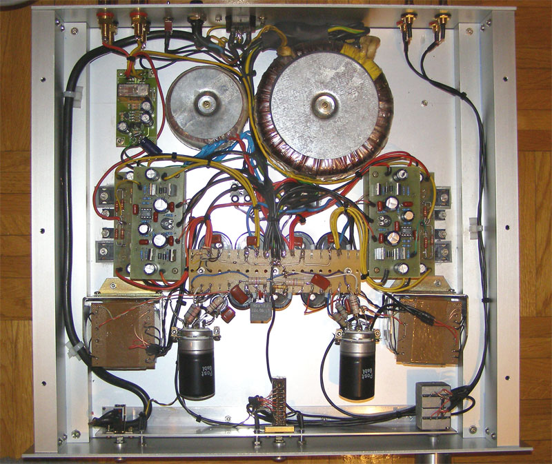
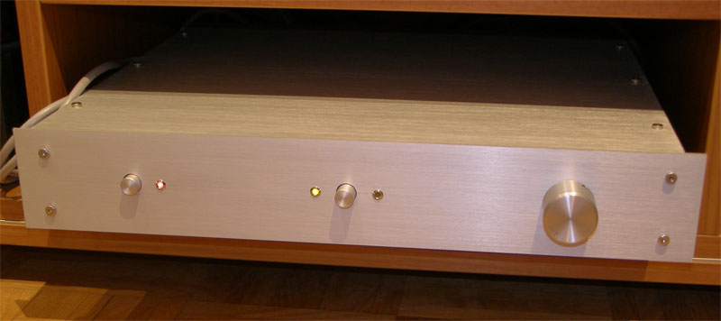
In the meantime, I have managed to bring my Academia project to completion and am now happily enjoying the fruits of my labor. As I said in an earlier post, Academia is a hybrid amplifier that consists of a tube driver input stage and your error correction output stage. The pictures below show the finalized version. I am planning to publish more details and measurements presently, on my personal website. So far, my listening impressions have been very positive. The amplifier is dead silent, with no thumps, hum, background noise or audible oscillation. It is very natural-sounding, with a soundstage which is airy, open, well-defined and strikingly detailed. In short, I am enjoying it very much. Thank you.
Regards,
Milan
First off, I wish to thank you once again for generously and tirelessly sharing your wealth of knowledge, expertise and experience with the rest of us, despite our somewhat peculiar and at times less than perfect combination of class and sass.
In the meantime, I have managed to bring my Academia project to completion and am now happily enjoying the fruits of my labor. As I said in an earlier post, Academia is a hybrid amplifier that consists of a tube driver input stage and your error correction output stage. The pictures below show the finalized version. I am planning to publish more details and measurements presently, on my personal website. So far, my listening impressions have been very positive. The amplifier is dead silent, with no thumps, hum, background noise or audible oscillation. It is very natural-sounding, with a soundstage which is airy, open, well-defined and strikingly detailed. In short, I am enjoying it very much. Thank you.
Regards,
Milan
moamps said:Let's make you blush some more then, Bob.
First off, I wish to thank you once again for generously and tirelessly sharing your wealth of knowledge, expertise and experience with the rest of us, despite our somewhat peculiar and at times less than perfect combination of class and sass.
In the meantime, I have managed to bring my Academia project to completion and am now happily enjoying the fruits of my labor. As I said in an earlier post, Academia is a hybrid amplifier that consists of a tube driver input stage and your error correction output stage. The pictures below show the finalized version. I am planning to publish more details and measurements presently, on my personal website. So far, my listening impressions have been very positive. The amplifier is dead silent, with no thumps, hum, background noise or audible oscillation. It is very natural-sounding, with a soundstage which is airy, open, well-defined and strikingly detailed. In short, I am enjoying it very much. Thank you.
Regards,
Milan
What a beutiful piece of work! I wish I could build amplifiers that are as pleasing to look at! Tell us more about the design. Thanks fo the pics!
Bob
Thanks guys for such positive feedback. I have to share the credit for my more recent chassis designs with my wife, who is my sternest critic and my greatest supporter.
As for more details about the topology, I still have to do all the measurements and experiment a bit more with different parts brands and tube connections to see what the maximum I can get out of the amplifier really is. There is no "prior art" for it so I am pretty much left to my own devices to figure things out and conclusively determine what may work best. These things take time so please bear with me. Once I am ready, I will publish the findings on my personal website.
Anyway, I hope my project would encourage other DIYers to show off their implementations of the error correction circuit and share their experience.
Regards,
Milan
- Home
- Amplifiers
- Solid State
- Bob Cordell Interview: Error Correction