A fascinating and, apparently, more voltage efficient way of defining the error correction loop's load impedance is used by Hawksford in figure 1-2 on page 10 here:
http://www.essex.ac.uk/ESE/research/audio_lab/malcolmspubdocs/C82 Non-switching amplifier.pdf
http://www.essex.ac.uk/ESE/research/audio_lab/malcolmspubdocs/C82 Non-switching amplifier.pdf
Andy_c, see fig. A1a here:
http://www.essex.ac.uk/ESE/research...wer amplifier current dumping enhancement.pdf
http://www.essex.ac.uk/ESE/research...wer amplifier current dumping enhancement.pdf
Re: Re: Bad Mike!
The system appears quite intolerant to deviations from this criteria, with very small (100ppm deviations) causing a disproportionate increase in THD.
mikeks said:...... the product of the summers gains must be unity for error cancellation.
The system appears quite intolerant to deviations from this criteria, with very small (100ppm deviations) causing a disproportionate increase in THD.
traderbam said:
The outter loop gain of the EC will reveal the cause of the peaking. Would you measure the outter loop gain with the 2uF and tell me the unity-gain f and the phase margin?
When I do this simulation with the Cordell model, nulled, the unity gain f is 750kHz with 1 deg of margin. Pretty unstable - no wonder an output L is mandatory. To resolve this the outter loop phase margin needs to be widened by at least 45 deg.
Possible...but tricky.
That's an interesting idea. I've been stuck in the "inner loop" rut, but it looks like the outer loop approach is a good one to take here.
I just did the sim with the Cordell model in the "as posted" conditon with a 2 uF load. Result was an outer loop unity loop gain frequency of 658 kHz with a phase margin of 5 deg. With the current project I'm working on, I get an outer loop unity loop gain frequency of 570kHz with a phase margin of 78 deg. This is also with a 2 uF load.
jcx wrote:

You will already have observed that the "null" adjust of Hawksford moves the LF gain up and down, which seems to be a source of satisfaction for many folk, but is superfluous. Being able to tune the loop gain phase margin, on the other hand, could be quite useful.
Brian
I agree. The maths agrees. Common-sense agrees. How come you are gifted enough to see this?No physical realization of linear error correction can “beat” the performance limits imposed by the finite gain-bandwidth of the circuitry.
If for instance we have 20 MHz single pole ”unity gain” summer circuit then its accuracy at 20 KHz is 1/1000 and it is therefore not capable of “100% cancellation in principle"
You will already have observed that the "null" adjust of Hawksford moves the LF gain up and down, which seems to be a source of satisfaction for many folk, but is superfluous. Being able to tune the loop gain phase margin, on the other hand, could be quite useful.
Brian
Andy_c wrote:
When you apply global fb the phase shift of the global loop components must be added to the phase shift of the EC. If the global feedback has unity gain at 570kHz and no phase shift (unrealistic) then the whole amp won't show much/any overshoot in the sim. So it is no surprise that any reasonable amount of global feedback destabilizes it.
How much overshoot do you see with the global feedback applied and what is the GB of the system?
You should be glad that your new project has a good amount of phase margin. In a simple two-pole system you need >76 deg of phase margin to eliminate overshoot as you know. Of course this isn't a simple two pole system so more may be needed. Can you see how much overshoot the output stage has on its own, if any?I just did the sim with the Cordell model in the "as posted" conditon with a 2 uF load. Result was an outer loop unity loop gain frequency of 658 kHz with a phase margin of 5 deg. With the current project I'm working on, I get an outer loop unity loop gain frequency of 570kHz with a phase margin of 78 deg. This is also with a 2 uF load.
When you apply global fb the phase shift of the global loop components must be added to the phase shift of the EC. If the global feedback has unity gain at 570kHz and no phase shift (unrealistic) then the whole amp won't show much/any overshoot in the sim. So it is no surprise that any reasonable amount of global feedback destabilizes it.
How much overshoot do you see with the global feedback applied and what is the GB of the system?
traderbam said:When you apply global fb the phase shift of the global loop components must be added to the phase shift of the EC.
I don't follow. Even though the unity loop gain frequency of the error correction loop is only 570 kHz, the -3 dB bandwidth of the output stage itself is about 2.3 MHz with the capacitor and almost 23 MHz with an 8 Ohm load (though it has about 108 deg phase lag there). So it doesn't behave as a classical feedback system in that sense.
How much overshoot do you see with the global feedback applied and what is the GB of the system?
I'm still working on the rest of the design
") . I started with the output stage and am working backwards. I've done some experiments with an idealized VAS and input stage, along with a variant of Bob's lead compensation that bypasses the output stage at high frequencies. That's it so far.
. I started with the output stage and am working backwards. I've done some experiments with an idealized VAS and input stage, along with a variant of Bob's lead compensation that bypasses the output stage at high frequencies. That's it so far.Andy_c wrote:
Does the output stage overshoot at all on its own into 2uF?
Sorry, you are quite right. I need to go to bed. So you need to see what the phase response is of the output stage vs f with the dreaded 2uF attached, then add this phase to the global loop phase, once you've designed it.I don't follow. Even though the unity loop gain frequency of the error correction loop is only 570 kHz, the -3 dB bandwidth of the output stage itself is about 2.3 MHz with the capacitor and almost 23 MHz with an 8 Ohm load (though it has about 108 deg phase lag there). So it doesn't behave as a classical feedback system in that sense.
Does the output stage overshoot at all on its own into 2uF?
With the output inductor, resistor, zobel, etc., the load seen by the amp as far as computing global loop gain is very benign. I'm not messing with a design without output inductor. Also, the series R-C from VAS to inverting input does an amazing job to reduce the output stage's phase lag contribution to the loop gain at high frequencies. I had to do a variant of this design to get a realizable C value though.
I'll look at the overshoot later and report back.
I'll look at the overshoot later and report back.
mikeks said:LTSpice schematics please.
The LT-Spice files for what I think is an Error-Correcting type of opamp/chipamp-based power amplifier design that I threw together are (at least temporarily) at:
http://www.fullnet.com/u/tomg/EC_Amp.asc
and
http://www.fullnet.com/u/tomg/opa541e.sub
I used the OPA541 model only because I can not find any models for the LM1875 OR LM3875, which should be able to perform better. And, no doubt, this system could perform better with different opamps. This version uses the LT1122, for no particular reason except that it was included in LT-Spice's standard library of models.
For some reason, it needs to be run using LT-Spice's Alternate Solver, usually.
You'll also notice that I lazily inserted ideal DC voltage sources to trim out the opamps' output offset voltages. However, they don't appear to make any significant difference. And I put parasitic caps across most of the resistors, but forgot to do most of the ones in the feedback loop.
I did add a capacitor, C4, in parallel with the resistor that takes the feedback to the summer, which, IIRC, seems to have improved the transient response, stability, and the THD figures, significantly. But I don't know if the amp is still a "pure" error-correcting type, with that cap. Without the cap, I think the feedback loop's gain has to be reduced, for the system to be stable.
I have not tested this very thoroughly. And it also doesn't have much RF filtering, yet, which I'm guessing it might need, if it were built.
- Tom Gootee
gootee said:
The LT-Spice files for what I think is an Error-Correcting type of...
Or, maybe it's not an EC type, after all. It doesn't seem to be in the form of the original figure 1.
- Tom Gootee
gootee said:Or, maybe it's not an EC type, after all. It doesn't seem to be in the form of the original figure 1.
- Tom Gootee
OK: There is a newer version that is more well-balanced:
http://www.fullnet.com/u/tomg/EC_Amp.asc
- Tom Gootee
Andy_c,
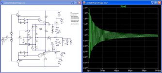
Here's the 1V step input response of the Cordell model when driving a 2uF cap, with near optimum null. The ringing reduces if the capacitance is reduced: 1nF gives 3% overshoot.
The ringing will reduce if the PFB is reduced in one direction from its peak, but will increase in the other. This is because the phase of the PFB loop changes through the "null" point. Go too far the wrong way and you'll have your own radio station.
Brian
Attachments
lumanauw said:
I wonder why people always test with stability towards 2uF capacitor?
Where does this test coming from?
This is a setup procedure for professional amp.
It only uses 0.47uF max and still allows ringing.
Hey boys! ... and eventual girls that read my letters ....
What I have figured out all by myself
( so that's why it may not be correct = Warning )
As power amplifier standard is 8 Ohm load and with a cap 2uF in parallel to load
1/( 2 x 3.14 x 2.0E-6 x 8 ) and f will be ~ 9947Hz ( 10 kHz )
Gives a resonance frequency within the upper audio band, <=20kHz
If we take 0.47uF. 1/( 2 x 3.14 x 0.47E-6 x 8 ) and f ~ 42.3 kHz
This test should then be possible for use with a modern extended upper bandwidth limit
= all them excessive fast audio power amps.
While in those days when 2 uF standard test came into practice
they wanted to make sure those amps had a good gain at freq in question.
This is my, lineup, own explanation.
Let me quote a professor in electronics,
and it is not one of our dear trio: Bob or Nelson or John:
.. a 2 uF capacitor.
This is a test that I learned from reading Bascom King's reports
on amplifiers for Audio (rip) magazine back in the '70s
This is in line with my own thinking, that the 2uF test, is an old thing.
When 20-40.000 Hertz and DC-coupling of output!!!
was still a new and ultimate sales argument!
But the 2uF test still is valid, as most amplifiers today also have a good output in band 10kHz-20kHz.
regards
lineup
Appendix A. ------------------------------------------------------------------
Web Source:The amplifier will drive a 4 ohm load to full power without current limiting. Depending on the power supply regulation, the output power with a 4 ohm load is as great as twice the power with an 8 ohm load. With loads lower than 2 ohms, the protection circuits limit the maximum output current, and thus the output power, to protect the output transistors. The amplifier is stable with capacitive loads and will drive electrostatic loudspeakers with no problems.
A good indicator of an amplifier sound quality is its ability to drive a capacitive load. The classic example of a capacitive loudspeaker transducer is the electrostatic transducer. Another is the piezoelectric transducer used in some horn tweeters. I have heard of amplifiers overheating when driving arrays of these tweeters. No doubt the circuits were oscillating. A third source of load capacitance that is often overlooked is the loudspeaker cable. Some of the so-called "high definition" cables are designed to minimize the series inductance. Because the series inductance per unit length multiplied by the shunt capacitance per unit length is a constant that is equal to the reciprocal of the velocity of light squared, minimizing the inductance maximizes the capacitance. Therefore, these cables can exhibit a high shunt capacitance. For this reason, I generally do not recommend them. I have heard of a certain "high-end" amplifier, which is no longer made, smoking when they are connected to its output, even with no signal input. A former student, when he was working for Panasonic, performed a listening test in their "high-end" listening room to see if there was any audible difference between a "high definition" cable and ordinary zip cord. He said that the listeners were in agreement that the high-frequency response was better with the zip cord, no doubt because the high capacitance of the "high definition" cable.
The Low TIM amplifier is stable with capacitive loads. I have tested it with a 2 uF capacitor. This is a test that I learned from reading Bascom King's reports on amplifiers for Audio (rip) magazine back in the '70s, and it is probably the worst load that I know of.
Because some amplifiers become unstable with a capacitor for a load, I have seen the test made with a resistor, e.g. a 2 ohm resistor, in series with the capacitor. This is cheating. It does not indicate the stability of the amplifier to a capacitive load. The first time I tested my prototype Low TIM amplifier with a 2 uF capacitor, it blew the 0.33 ohm 5 W emitter degeneration resistors in series with the output transistors. I suspect the circuit was oscillating. Either the resistors couldn't handle the current or the circuit was oscillating. I suspect the latter.
http://users.ece.gatech.edu/~mleach/lowtim/bckgrnd.html
Low TIM Amplifier design background
by
Professor W. Marshall Leach, Jr.
of
Georgia Institute of Technology
School of Electrical and Computer Engineering
Graduate Teaching Assistant, 1968-1972
Assistant Professor, 1972-1976
Associate Professor, 1976-1983
Professor, 1983-Present
The bam challenge
This is the hypothesis that MUST BE TRUE if the belief that "error correction" cancels output error and is not just NFB in disguise is true.
I challenge ANYONE here to find me ANY linear function L that meets this claim for ANY non-linear function N.
Brian
Hint: you are wasting your time trying.
Hypothesis:
A non-linear function's output can be transformed into the inverse of that function using additon and subtraction alone.
Example:
A function N(x) is non-linear.
There exists a linear function, L[x, N(x)] = the inverse of N(x), so that N{L[x, N(x)]} = x
This is the hypothesis that MUST BE TRUE if the belief that "error correction" cancels output error and is not just NFB in disguise is true.
I challenge ANYONE here to find me ANY linear function L that meets this claim for ANY non-linear function N.
Brian
Hint: you are wasting your time trying.
Re: The bam challenge
You need to establish in your mind what you mean by ''non-linear''
E.G. It could be argued that:
PWM is inherently non-linear. Period.
An NE5534 op. amp is inherently linear with ''small'' amounts of distortion.
A complementary emitter follower biased into class-AB is inherently linear with ''small'' amounts of distortion.
Sort out your definitions.
traderbam said:
This is the hypothesis that MUST BE TRUE if the belief that "error correction" cancels output error and is not just NFB in disguise is true.
I challenge ANYONE here to find me ANY linear function L that meets this claim for ANY non-linear function N.
Brian
Hint: you are wasting your time trying.
You need to establish in your mind what you mean by ''non-linear''
E.G. It could be argued that:
PWM is inherently non-linear. Period.
An NE5534 op. amp is inherently linear with ''small'' amounts of distortion.
A complementary emitter follower biased into class-AB is inherently linear with ''small'' amounts of distortion.
Sort out your definitions.
Re: The bam challenge
I suspect nobody claimed ''error correction'' isn't NFB; rather, it just isn't NFB in the commonly understood sense.
With the usual single-ended NFB, loop-transmission does NOT increase with the quantity (''error'') we wish to eliminate, while with error-cancellation-by-NFB, loop transmission is directly proportional to extracted error.
traderbam said:......."error correction" cancels output error and is not just NFB in disguise is true.
I suspect nobody claimed ''error correction'' isn't NFB; rather, it just isn't NFB in the commonly understood sense.
With the usual single-ended NFB, loop-transmission does NOT increase with the quantity (''error'') we wish to eliminate, while with error-cancellation-by-NFB, loop transmission is directly proportional to extracted error.
- Home
- Amplifiers
- Solid State
- Bob Cordell Interview: Error Correction