Found some time today to do some measurements on my EC output stage.
First the diagram. Purpose was to see if I can make an output stage that acts like an 'ideal' gain-of-one power stage that you could hang on a Vas stage with minimal loading, then run it without overall feedback. The output transistors are a refinement of the Toshiba thermal tracks.
Jan Didden
First the diagram. Purpose was to see if I can make an output stage that acts like an 'ideal' gain-of-one power stage that you could hang on a Vas stage with minimal loading, then run it without overall feedback. The output transistors are a refinement of the Toshiba thermal tracks.
Jan Didden
Attachments
Your results are very good indeed...
I wonder how frequency compensation is done, as I guess the rise in THD vs freq. is because of it. Some sorts of compensating EC does cause mismatch in "matched to ideally cancel distortion" resitors.
regards
Adam
P.S. Do you check your mailbox (-boxes?) from time to time")
I wonder how frequency compensation is done, as I guess the rise in THD vs freq. is because of it. Some sorts of compensating EC does cause mismatch in "matched to ideally cancel distortion" resitors.
regards
Adam
P.S. Do you check your mailbox (-boxes?) from time to time
Hi Adam,
I use 36pF across the input resistor (R25 I think it is) to roll of the EC above 600 or 700kHz. No freq compensation otherwise.
Edit: The rising THD with freq is due to the current conveyor. Here you win, there you lose...
PS No recent messages from you in my inbox, AFAICS
Jan Didden
I use 36pF across the input resistor (R25 I think it is) to roll of the EC above 600 or 700kHz. No freq compensation otherwise.
Edit: The rising THD with freq is due to the current conveyor. Here you win, there you lose...
PS No recent messages from you in my inbox, AFAICS
Jan Didden
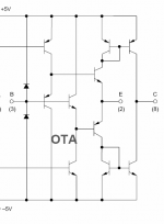
CCII's are available in various disguises. They are also known as diamond transistors, transconductance amplifiers and as front-ends in so called 'current feedback opamps'.
But the basic structure is always the same. This particular one is from the OPA660 data sheet.
The X-terminal is the 'base', the Y-terminal is the 'emitter' and the current output terminal Z is the 'collector'.
Jan Didden
But the basic structure is always the same. This particular one is from the OPA660 data sheet.
The X-terminal is the 'base', the Y-terminal is the 'emitter' and the current output terminal Z is the 'collector'.
Jan Didden
Attachments
Fanuc said:I wonder if Hawkesford error correction is better than Quad's "current dumping" if the Quad scheme was properly optimised. Some of the op amps around today are much better than was in the original 405 power amp.
Plus the Quad patent has probably expired anyway.
In *theory*, both Hawksford EC and Quad CD can deliver zero distortion. Something that negative feedback cannot.
How close you get to zero is all in the implementation of course, and in *practise* you'll never get to zero. Quad CD depends on two impedance ratios being equal, and each ratio consists of a resistor and a recative component (cap for one part of the bridge, inductor for the other).
Hawksford EC only depends on the ratio of two resistors being unity, so my bet would be with Hawksford. That's why I use it in my amp as described above.
Jan Didden
Charles Hansen said:[snip]First of all, "error correction" is simply a feedback loop with gain in the feedback direction. The only way that you can keep this type of thing from oscillating like a radio station is to only include a very short part of the circuit (not the whole thing.)
[snip]
Hi Charles,
I have to take exception to the above. In Hawksford-style error correction (assuming that is what you refer to) there is no gain in the feedback path. This is easy to demonstrate. You can actually cut the error correction loop and the amp gain doesnot change by more than a few percent. Also, the error that is fed back isn't amplified either, but is returned in (ideally) precise unity.
I am aware that an error correction loop can be seen as a combination of pos and neg feedback, and that this is reason for some to say: "see, it uses pos feedback, so there is gain!". But that's a no-brainer: that's like saying that 1 is the difference between 101 and 100 and therefore concluding that 1 is a Large Number....
It's actually hard to get it to oscillate, anyway...
I posted my error correction output stage in Bob's error correction thread.
Jan Didden
janneman said:Hi Charles,
I have to take exception to the above. In Hawksford-style error correction (assuming that is what you refer to) there is no gain in the feedback path. This is easy to demonstrate. You can actually cut the error correction loop and the amp gain doesnot change by more than a few percent. Also, the error that is fed back isn't amplified either, but is returned in (ideally) precise unity.
I am aware that an error correction loop can be seen as a combination of pos and neg feedback, and that this is reason for some to say: "see, it uses pos feedback, so there is gain!". But that's a no-brainer: that's like saying that 1 is the difference between 101 and 100 and therefore concluding that 1 is a Large Number....
It's actually hard to get it to oscillate, anyway...
I posted my error correction output stage in Bob's error correction thread.
Jan Didden
Hi Jan,
I'm sorry to say, but I agree with Charles. Theoretically, EC is nothing else than reducing the distortion to zero by means of a FB circuit with infinite gain. If you don't believe me, just break the loop from output to the node of R42 and R43 in Bob's example. You'll see a loop gain in the order of 40 to 50 dB. So, Charles isn't wrong, it is just a different point of view.
Cheers, Edmond.
estuart said:
Hi Jan,
I'm sorry to say, but I agree with Charles. Theoretically, EC is nothing else than reducing the distortion to zero by means of a FB circuit with infinite gain. If you don't believe me, just break the loop from output to the node of R42 and R43 in Bob's example. You'll see a loop gain in the order of 40 to 50 dB. So, Charles isn't wrong, it is just a different point of view.
Cheers, Edmond.
Hi Edmond,
I'm not going to speculate on someone else's circuit. And it's off-topic here anyway; I just HAD to react because Charles brought it up.
BUT I am quite interested to follow this up in Bob's error correction thread. Please take a look at my circuit, here:
http://www.diyaudio.com/forums/showthread.php?postid=1273756#post1273756
Please tell me where you want to cut the loop to show the loop gain introduced by the error correction loop.
Cheers, Jan Didden
janneman said:Hi Edmond,
I'm not going to speculate on someone else's circuit.
And it's off-topic here anyway; I just HAD to react because Charles brought it up.
BUT I am quite interested to follow this up in Bob's error correction thread. Please take a look at my circuit, here:
http://www.diyaudio.com/forums/showthread.php?postid=1273756#post1273756
Please tell me where you want to cut the loop to show the loop gain introduced by the error correction loop.
Cheers, Jan Didden
Hi Jan,
True, it's off-topic here, but for the same reason as you did, I just HAD to react too.
Regarding speculating on someone else's circuit, come on Jan, everybody involved with EC knows about Bob Cordell's EC circuit, so you (should) know exactly where I've broken the loop.
BTW, I have already downloaded your schematic a couple of days ago. When I have more time, I'll have a closer look at it.
Cheers, Edmond.
estuart said:
Hi Jan,
True, it's off-topic here, but for the same reason as you did, I just HAD to react too.
Regarding speculating on someone else's circuit, come on Jan, everybody involved with EC knows about Bob Cordell's EC circuit, so you (should) know exactly where I've broken the loop.
BTW, I have already downloaded your schematic a couple of days ago. When I have more time, I'll have a closer look at it.
Cheers, Edmond.
Hi Edmond,
I assume you mean breaking the connection to R42, 43 in Bob's article fig 12? So you effectively disconnect the inverting input to summer S1 in his fig 11?
I'm not sure what that proves though. You can't take a system with combined pos and neg feedback, delete one of the two and then say: see, it's extra loop gain! or another statement.
Are you familiar with the writings of Gerald Graeme of Burr Brown (before they were eaten by TI) in EDN and his books? He has given ways to calculate the effective feedback factor in a loop composed of any number of pos and neg feedback loops.
Moderators: please can you split these posts to Bob's EC thread?
Jan Didden
janneman said:Hi Edmond,
I assume you mean breaking the connection to R42, 43 in Bob's article fig 12? So you effectively disconnect the inverting input to summer S1 in his fig 11?
Hi Jan,
Yes, I think so. Actually, I'm referring to his article published in the Siliconix Mospower Applications Handbook, where these figures are numbered 8 respectively 9.
janneman said:I'm not sure what that proves though. You can't take a system with combined pos and neg feedback, delete one of the two and then say: see, it's extra loop gain! or another statement.
Well, as a matter of fact, I did delete the front-end and AC grounded the input of the EC circuit. Under these conditions I observed the loop gain at node R42/R43, which was quite high.
You are right regarding the role and influence of the negative FB loop. If also taken into account, the aforementioned loop gain drops dramatically (to unity). But that wasn't my point, as it seems that quite a lot of people test and evaluate their EC output stage in isolation and under these conditions I believe my statement is valid. Please, correct me if I'm wrong.
janneman said:Are you familiar with the writings of Gerald Graeme of Burr Brown (before they were eaten by TI) in EDN and his books? He has given ways to calculate the effective feedback factor in a loop composed of any number of pos and neg feedback loops.
Jan Didden
No. If you have any in electronic form, I'd love to get a copy
Cheers, Edmond.
estuart said:[snip]Well, as a matter of fact, I did delete the front-end and AC grounded the input of the EC circuit. Under these conditions I observed the loop gain at node R42/R43, which was quite high.
You are right regarding the role and influence of the negative FB loop. If also taken into account, the aforementioned loop gain drops dramatically (to unity). But that wasn't my point, as it seems that quite a lot of people test and evaluate their EC output stage in isolation and under these conditions I believe my statement is valid. Please, correct me if I'm wrong.
[snip]
I think I can agree to that. Need to look at it in more detail. My point was (and is) that you need to look to the system in its totality, and try to come up with the effective feedback factor. You mentioning that the total loop gain drops to unity if you take both the pos and neg feedback loop into account is exactly what I found also.
Als, I have been playing with feedback systems 25+ years, and you get a feeling for their stability (or lack thereof). A proper EC system is completely different, it's docile ("mak" in dutch). Even if I have it wrong in theory, it IS quite different from all the other feedback variations I have dealt with. There IS something to this, I strongly believe that.
estuart said:[snip]No. If you have any in electronic form, I'd love to get a copy
Cheers, Edmond.
I need to scan it, I'll see if i can do it tomorrow.
Jan Didden
janneman said:Please tell me where you want to cut the loop to show the loop gain introduced by the error correction loop.
Hi Jan,
Here is an old post from this thread that might clear up some of the loop gain stuff. If you break open the loop in a different spot from where I did in that post, (say, inside the EC diff amp itself), you can get a loop gain that approaches zero. But where I broke it, the loop gain approaches infinity.
estuart said:
Hi Jan,
I'm sorry to say, but I agree with Charles. Theoretically, EC is nothing else than reducing the distortion to zero by means of a FB circuit with infinite gain. If you don't believe me, just break the loop from output to the node of R42 and R43 in Bob's example. You'll see a loop gain in the order of 40 to 50 dB. So, Charles isn't wrong, it is just a different point of view.
Cheers, Edmond.
Hi Edmond,
I think that both ways of looking at EC are valid and necessary, as each has its value in exposing the behavior of the approach.
Even if it is viewed as nothing more than a negative feedback loop inside of which we put a unity gain positive feedback loop to get theoretically infinite forward gain, the technique is extremely effective and no more difficult to compensate than an ordinary feedback loop, if you know what you are doing, notwithstanding Charles' assertion that stability is a problem.
Part of its advantage comes from the fact that it is an extremely tight, fast feedback loop (or whatever) around the output stage.
By the way, the best reference to my error correction work is the JAES paper that is available as a pdf on my web page at www.cordellaudio.com under "published papers."
Cheers,
Bob
- Home
- Amplifiers
- Solid State
- Bob Cordell Interview: Error Correction