Hi Mike,
I am so impressed by the thought of cascoding the drivers. This will linearize the current stage more. Whether it's truly helpful or not is hard to say. We really have to try this.
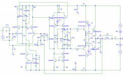
This is not really a Symasym in concept, but very worthwhile to try. The cascodes can be bypassed so a direct comparison can be made stage by stage. Therefore it's a fantastic proof of concept, or study amplifier. If all cascodes end up being used it may be a great higher power amplifier (that everyone is asking for). Actually, even if only the front end ones and Vas are used we now have a higher power amplifier.
I'd say do a board this way, study it and make a final determination at the end. It will be a great learning tool I think. make room for more output pairs dude!
-Chris
I am so impressed by the thought of cascoding the drivers. This will linearize the current stage more.
Whether it's truly helpful or not is hard to say. We really have to try this.This is not really a Symasym in concept, but very worthwhile to try. The cascodes can be bypassed so a direct comparison can be made stage by stage. Therefore it's a fantastic proof of concept, or study amplifier. If all cascodes end up being used it may be a great higher power amplifier (that everyone is asking for). Actually, even if only the front end ones and Vas are used we now have a higher power amplifier.
I'd say do a board this way, study it and make a final determination at the end. It will be a great learning tool I think. make room for more output pairs dude!
-Chris
my votes:
keep the cascodes on the input jfets.
trash the cascode current sink for the diff amp - i'd just stick with a simple bipolar transistor and use a red LED for reference voltage.
keep the cascode on the second stage diff amp. there's probably some clever sharing to be done between current sources and voltage references.
keep the cascode on the second stage's current mirror.
trash the cascode on the output drivers.
mlloyd1
Hi Al, the feedback is taken before zobel on the board, only on schematic its taken after. (in sims the same analog node anyway)
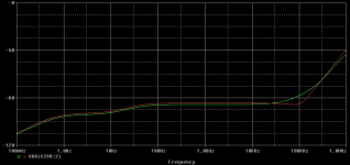
Chris, according to sims the cascoded drivers heavily reduce compression at high power levels, as the hfe of the drivers does no longer change with swing. At low power levels they only increase psrr ~50db at 10khz.
Fernando, there is one problem with increasing power for symasym, especially up to 150w into 8ohms. To get 150w/8r you need supply rails of at least ~55v. Also bias in vas needs to be increased to keep up with the increased current demand from outputstage. This will result in increased dissipation levels of ~2.5, toasting the to92 devices used in the vas. With 55v supply, the mpsa18 must be replaced by higher voltage types. bc546 should do it.
Also, at least 2 outputpairs are necessary, 3 pairs if you still want to drive 4ohms. Are you sure 60watts are not enough ?
Al, Chris, the 1.87v in the vas represent a green LED, maybe simply feed it with a 22k res. Don't forget basestoppers, or the cascodes might oscillate.
Mike
Hi Mike,
I have had good luck with LED references so far, but I do bypass them.
I think an experimental PCB board should be done, three output pairs. (may as well go for it) The CCS may be simplified as mlloyd1 suggested. Can you sim the change?
-Chris
Edit: Pavel, just read your post. I agree. I think a test board should be done first though to explore the options and show which ones actually are audible. Mileage may vary on different systems.
mlloyd1 said:my votes:
keep the cascodes on the input jfets.
trash the cascode current sink for the diff amp - i'd just stick with a simple bipolar transistor and use a red LED for reference voltage.
keep the cascode on the second stage diff amp. there's probably some clever sharing to be done between current sources and voltage references.
keep the cascode on the second stage's current mirror.
trash the cascode on the output drivers.
mlloyd1
mlloyd, about the cascoded current sink to the diffamp, i just chosed that one because it seemed to have the best psrr with reasonable complexity. Of course the actual construction is nuts, the upper ccs needs to be same quality as the lower...

One thing is for sure, i'll never again use the 2diode style ccs, it's psrr was poor enough to not keep stable biasing. Have to verify LED-style in real world.
What's wrong with the cascoded drivers ?
Of course each of the cascodes needs to be checked independently if it improves sound at a level to justify added complexity.
One of my earlier amps used cascoded vas, it was everything but quite...

Al, Chris, i forgot, in first diffamp a set of anti paralell diodes (1n4148) between the 2 680ohms is necessary to avoid heavy saturation of vas devices during clipping. A "negative" effect of the cascoded vas in symasym would be the complete loss of the dominant 2nd harmonic.
Mike
anatech said:Hi Mike,
I have had good luck with LED references so far, but I do bypass them.
I think an experimental PCB board should be done, three output pairs. (may as well go for it) The CCS may be simplified as mlloyd1 suggested. Can you sim the change?
-Chris
Edit: Pavel, just read your post. I agree. I think a test board should be done first though to explore the options and show which ones actually are audible. Mileage may vary on different systems.
Chris, i can't simulate LEDs, have no model... But if they are at least up to zeners regarding voltage stability, they should be better than the 2bjt-ccs i used for symasym. Do you bypass them with a cap ? That's dangerous, you should add a basestopper. (Risk of local oscillation, >100mhz,if such problem is not detected, amp will sound bad without obvious reason, this oscillation is not visible at output)
I have a weird feeling that we will skip all cascodes.

But i have hopes, symasym5 has at least one cascode, and it's dead quite.
Mike
Hi Mike,
The forward drop of a red LED matches a BJT closely. They make good references that track with temperature. I haven't seen any 100 MHz + oscillations at all. My scope has a 100 MHz bandwidth. Your caution will be considered. I just haven't had a problem ...... yet.
-Chris
The forward drop of a red LED matches a BJT closely. They make good references that track with temperature. I haven't seen any 100 MHz + oscillations at all. My scope has a 100 MHz bandwidth. Your caution will be considered. I just haven't had a problem ...... yet.
Let's make the multi cascode unit first and find out through experimentation. You may be right, or wrong.I have a weird feeling that we will skip all cascodes.
Not if it's cleaner and more dynamic!A "negative" effect of the cascoded vas in symasym would be the complete loss of the dominant 2nd harmonic.
-Chris
Yes, right now symasym has a "dominant" 2nd harmonic. The cascoded version looses that completely. As a side effect the very high order harmonics reduce (through the nfb harmonic upfolding effect)
I don't know how the sound changes loosing the 2nd harmonic.
But my experience showed that reducing even order harmonics made the sound cleaner/better.
The 2nd harmonic is created by the effect that the right transistor in 2nd diffamp sees full voltageswing, the left is fixed.
Openloop bandwidth will/should not change with these cascodes.
Mike
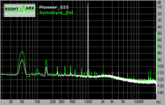
I attached a direct comparison between setup and amp distortion.
White is without symasym, green with symasym (jfet version). The only measurable harmonic here is the 2nd (~-95db).
About the HF-garbage, the first line is 15565hz, the PAL-horizontal freq, the second one, i don't know.
Looks like a resonance, but as PMAs measurings do not show it i am not really worried.
Mike
Attachments
Considering you use quite high gain for the whole amp (so input tail AC voltage is relatively small), and a differential VAS, (so changes in Vds of the input FETs are symetrical and relatively small), an input cascode may not give you a usable advantage in distortion reduction apart from increased PSRR. If you do use it, I would not trust the voltage developed on the 5k resitor to be constant, making the cascode voltage follow the input pair tail voltage simply because the tail and top current sources will not AC track with their impedance, especially at higher frequencies. I would put a capacitor in parallel with it, and even so it would not be perfect
Since the input pair tail AC voltage is small, you may want to use another trick to insure that the tail CCS remains 'resistive' - which is, simply put a resistor in series with it. A further trick is to split this resistor into two resistors with double value, one per each source, then connect the sources with a third resistor - this way you have a single resistor to set if you wish to degenerate the input pair. This is dubious for a FET input but may prove usefull for anyone wishing to use a BJT input stage. If you don't want to use degeneration, simp[ly put a wire link instead of the S-S (or E-E) resistor.
If you are to use FETs for the input pair, consider upping the input stage tail current. It increases gm and makes delta Id smaller in comparison with the tail current, in essence you are working along less of the gm vs Id curve, so you get increased linearity. As discussed in the other thread, unlike BJTs, bias current is no problem with FETs
The VAS cascode and Wilson current mirror may be a very worthwhile addition. Because the current mirror pair and the differential pair see only small voltages across C-E, you can use different transistors for the current mirror proper and differential pair (BC546/556 come to mind), and the cascode transistors, which means you may be able to use transistors with a higher dissipation, or, for higher voltage rails, higher Vce max rating. This sort of setup may also disbalance the current mirror some (Wilson Cm stays perfectly balanced only if all transistors are the same) so you would still retain the second harmonic in the output
It remains to be seen if the virtues outweigh the vices for rail voltages where higher flexibility in choice of transistors for the VAS is not needed. There is more:
Although these cascodes increase PSRR, it remains a question wether a well chosen filtering scheme for the local rails of the input and VAS won't do sufficiently well at a much lower cost, not so much in parts, as in routing complexity, and places for a less equipped and experienced DIY-er to go wrong (local oscillations etc...).
Finally, adding cascodes for an amp that shares rails for the output and input stages will tend to reduce efficiency as the cascode voltage adds to rail loss... quite important for a relatively low power amp, especially since this rail voltage loss does nothing to improve the required SOA for the output pair, as it comes from the input stages.
Cascoding the drivers is, IMHO a bit problematic, simply because in a simulation you can easily hang a voltage source for the cascode, while in real life getting it 'floating' around with the driver emitter may not be easy at all, without introducing other problems. At best, it has to be some form of bootstraping, which would be better referenced on the output - you want to have all the emitter current of the drivers you can get. While at the subject of bootstrapping, it may be interesting to explore a configration where the drivers emitters are separately bootstrapped to the oposing rail, so they work into a 'current source'. Of course, this means introducing yet more large electrolytics to a sensitive spot...
Hi ilimzn,
Pavel, I think we are trying to go forward and retain the good parts of the Symasym. If we lose those, there is no point. You won't get any fights there.
-Chris
That is one thing I had in mind.If you are to use FETs for the input pair, consider upping the input stage tail current. It increases gm and makes delta Id smaller in comparison with the tail current, in essence you are working along less of the gm vs Id curve, so you get increased linearity. As discussed in the other thread, unlike BJTs, bias current is no problem with FETs
Pavel, I think we are trying to go forward and retain the good parts of the Symasym. If we lose those, there is no point. You won't get any fights there.
-Chris
- Status
- This old topic is closed. If you want to reopen this topic, contact a moderator using the "Report Post" button.
- Home
- Amplifiers
- Solid State
- Symasym - the sequel