Hello AndrewT
Sorry for my mistake not 50V p to p.
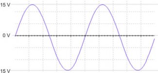
Max +/- 50V swing saw in oscilloscope.
That will be 100V p to p
100Vpp=50Vpk=50/(root2)Vrms or Vac = 35Vrms
Power delivered into a 4r load is
P=Vpk*Vpk/2/Load=50*50/2/4=312.5W
Maximum current when delivering this power is
Ipk=Vpk/Load=50/4=12.5Apk
That power & I peak cannot supply from my power supply.
I average saw in oscilloscope is +/- 30V
30Vpk=50/(root2)Vrms or Vac = 21.21Vrms
P=Vpk*Vpk/2/Load=30*30/2/4=112.5W
That may be possible for my power supply.
I think I must use sine wave generator for measure true power output.
Is that true ?
Can Output power vary because of frequency ?
Max 50V p to p.....50v peak / sqroot of 2 = about 35V RMS over 4 ohms is 35 squared / 4 is 306.25 W RMS.Is that true
Sorry for my mistake not 50V p to p.
Max +/- 50V swing saw in oscilloscope.
That will be 100V p to p
100Vpp=50Vpk=50/(root2)Vrms or Vac = 35Vrms
Power delivered into a 4r load is
P=Vpk*Vpk/2/Load=50*50/2/4=312.5W
Maximum current when delivering this power is
Ipk=Vpk/Load=50/4=12.5Apk
That power & I peak cannot supply from my power supply.
I average saw in oscilloscope is +/- 30V
30Vpk=50/(root2)Vrms or Vac = 21.21Vrms
P=Vpk*Vpk/2/Load=30*30/2/4=112.5W
That may be possible for my power supply.
I think I must use sine wave generator for measure true power output.
Is that true ?
Can Output power vary because of frequency ?
Thanks guys!
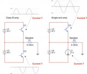
Every one said that the current was to low. To have the correct current, 3 Amp for the amp is it the same as – 1,5 amp negative side sin wave and + 1,5 amp on the positive side or …? (see picture with red questions.)
How is it with the class B amps? is it -1,5 over the PNP (– side) transistor and 1,5 over the NPN transistor (+ side), (see the picture). How is it with Single end where the whole signal is on one transistor and you have a current source? Should the current source was on the whole current 3 Amp or… (see picture.)
Attachments
This was not requested but turned out to be usefull!
Adding pk (zero to peak) or pp (peak to peak) as a suffix usually clarifies and avoids ambiguity.
Hi Prog,
firstly, get rid of your proposed 4ohm load.
8ohm speakers are a difficult enough load for an amplifier. Designing for true 4ohm ability just makes the job that much harder.
Each supply rail will see alternate peak currents of Ipk. That was the purpose of my presentation style.
The smoothing caps and any decoupling along the route supply most of the current spikes required by the load. The long term DC current comes from the transformer through the rectifier.
Hi Prog,
the ccs shown on your single ended amp carries constant current.
The load current is correctly shown as peaking at Ipk. But the arrow is pointing to the transistor, it should be pointing to the load.
The extra current, to supply the load, comes from the working output transistor.
It's current is Iq +-ILoad and can vary from zero (or almost zero as distortion increases badly as zero is approached) to two times Iq (again almost twice).
So much for all the erroneous references to constant current in a single-ended ClassA amplifier.
Hi Progg70, sorry if i sound rude, your questions are too fundamental, you really need to work out them on yourself. Without understanding how all these currents sum up, you will never be able to understand any electronics/electricity. You must learn that by understanding.
A few hints:
- Q2 is reversed, the emitter needs to show up.
- The current through a ccs is constant, that's what makes it a current source.
- Get perfectly familiar with ohms law, I = V/R, V = I*R, R = V/I
- Think of currents like flowing water. You know what current is flowing through the 4ohms. This current needs to be a sum of the currents from both transistors, but don't forget the sign ! (The direction of the current flowing)
An example for the single ended:
- outputvoltage +1v, current through 4ohm is 0.25a, current through upper transistor is 1.25a
- outputvoltage -1v, current through 4ohm is -0.25a, current through upper transistor is 0.75a
Mike
Kirchhoff's Current law:
http://www.physics.uoguelph.ca/tutorials/ohm/Q.ohm.KCL.html
With kind regards,
Klaas
http://www.physics.uoguelph.ca/tutorials/ohm/Q.ohm.KCL.html
With kind regards,
Klaas
You are a Jerk...as you can see, there are multiple visions about the subject
There are many variables that can fool the basic calculations, and even those calculations produce different results ..many results are provided by experienced people here.
The Watt meter will give the correct answer...we can go close with calculations...but as you see...where is the rigth answer?
I receive critics because made errors, if only perfect people could write in the forum you probable will se nobody...if we acept that there's a single correct answer, there are many making errors.
There are simple questions that have not a simple answer, as depends of this and that.
This show us that we have the need to exercise to be humble, as this simple question is showing me, and i hope showing to you to, that the correct answer may depends from other factors, and to colect all them is not so easy.
My vote goes for Michael, as the one has a lot of practice, not only theories...the one know the differences between calculations and real world data resultant of meterings....The humble factor in my point of view.
But, there are in this thread another practice monster...Anatech, this one had reparied more amplifiers than many of this thread could ever see in their lives...and one incredible good engineer, Janemann, as he is one of the forum references... and there are others that i did not mention.
regards,
Carlos
Lets try a new equation......different numbers  More watts.
4 ohm Speaker.
How much power output at 4 ohms, with power supply rails that are +/- 70V unloaded, but may drop to 54V under full load. Load goes to ground rail, so it is not bridged.
Tell me if this is right?!?!?
54V rail minimum.
-4V because of voltage drop of amp at clip.
________
50V peak output
*.707 to get RMS
__________
35.35V RMS output
35.35 squared = 1249.6225 / 4 ohms = 312.4WRMS or 624.8W Peak
Is this accurate?
More watts.4 ohm Speaker.
How much power output at 4 ohms, with power supply rails that are +/- 70V unloaded, but may drop to 54V under full load. Load goes to ground rail, so it is not bridged.
Tell me if this is right?!?!?
54V rail minimum.
-4V because of voltage drop of amp at clip.
________
50V peak output
*.707 to get RMS
__________
35.35V RMS output
35.35 squared = 1249.6225 / 4 ohms = 312.4WRMS or 624.8W Peak
Is this accurate?
Hi Prog,
a properly specified 8ohm speaker does not match this description
It is generally accepted that the minimum impedance of a speaker (anywhere in the frequency range) never falls below about three quarters to two thirds of the nominal impedance. Almost no-one builds to the DIN standard.
Speakers are a difficult load and they stress the output stages of amps particularly if the sinks are allowed to get hot. Wrongly specifying the speaker impedance can only exacerbate the problem.
But if retail amplfiers were designed to work well, rather than to a barely acceptable budget then the whole industry would have a better reputation, resulting in an ability to drive even difficult loads whin specification. Never EXPECT an amp to perform well when outside it's specified limitations, although some are very capable.
a properly specified 8ohm speaker does not match this description
If it goes this low it should be specified as a 4 to 8ohm speaker or at worst a 6ohm speaker.speakers go down to 4ohm and below in different frequency areas
It is generally accepted that the minimum impedance of a speaker (anywhere in the frequency range) never falls below about three quarters to two thirds of the nominal impedance. Almost no-one builds to the DIN standard.
Speakers are a difficult load and they stress the output stages of amps particularly if the sinks are allowed to get hot. Wrongly specifying the speaker impedance can only exacerbate the problem.
But if retail amplfiers were designed to work well, rather than to a barely acceptable budget then the whole industry would have a better reputation, resulting in an ability to drive even difficult loads whin specification. Never EXPECT an amp to perform well when outside it's specified limitations, although some are very capable.
Hi Ew,
I have an amp as bad (no, slightly better) than your example.
It is a very poorly specified example with a complete imbalance between the various stages of the amplifier. Yet it sounds quite nice into a speaker load about twice the specified minimum.
I would expect a well balanced design, if properly implemented, to achieve a peak voltage output into the specified load to be MUCH better than 20V less than the quiescent rail voltage. Mine is +-69Vrail falling to 55Vpk (into 8r) and to 49V (into 4r)and I think that 14V/20V loss is terrible.
The pair of transformers (per monoblock) are VA underspecified by a factor of about 1.5 to 2.
But your number crunching is correct, just aim higher.
- Status
- This old topic is closed. If you want to reopen this topic, contact a moderator using the "Report Post" button.
- Home
- Amplifiers
- Solid State
- Output power for a power amplifier