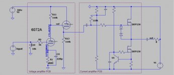
Here the new PCB and last schematic
I am producing some of this pcb to test it.
I think this circuit can give the best performances using on input MK132 Caddock or parallel out-phase metal 1% resistors.
The input capacitor should be Auricap, Z-Cap RED or better.
The output capacitor should be Jensen electr., Nichicon Super Through or BHC Slit Foil, no other choice.
Attachments
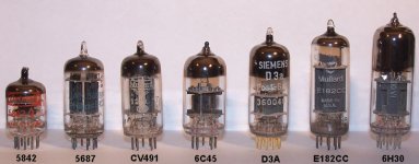
I think the best solution as voltage stage is vacuum tube stage.
I prefer a single tube like D3a or 6C45.
D3A specifications in triode connection:
filament voltage: 6.3V
filament current: 315mA
Max plate voltage: 200v
Max plate dissipation: 4.2w
Max cathode current: 33mA
Plate resistance: 1.9Kohm
Amplification factor: : 77
Max resistance in grid circuit: 0.5Mohm
6C45 specifications:
filament voltage: 6.3V
filament current: 440mA
Max plate voltage: 150v <<<<< it is lower than D3a
Max plate dissipation: 7.8w
Max cathode current: 52mA
Plate resistance: 1.2Kohm
Amplification factor: 52 ±16 <<<<< selection is necessary
Max resistance in grid circuit: 0.15Mohm
Here the schematic and relative pcb to create a cheap and good power supply for the vacuum tube voltage stage.
It use a virtual battery operation on anodic like the Power Follower and a soft start for filaments.
For some single tube configurations follow this link:
- http://www.audiodesignguide.com/Ibridone/index.html
- http://www.audiodesignguide.com/Ibridone/index3.html
Soon I will update also this project.
Attachments
Last edited:
Files
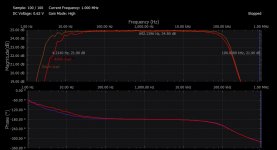
Here some files to produce the pcb and to make some simulations with LTspice.
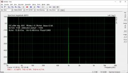
Follow the first configuration simulated on 8 and 4 ohm load:
Vcc=40V
Ibias=3A
IRFP150
Pd=40 x 3A = 120W
Vin=19Vp => 13.5Vrms
Vout = 18.5Vp -> 13.1Vrms
Rload = 8ohm
THD = 1.5%
Pout=13.1*13.1/8 = 21.5W
Vin=12Vp => 8.5Vrms
Vout = 12Vp -> 8.5Vrms
Rload = 4ohm
THD = 2%
Pout=8.5*8.5/4 = 18W
Here some files to produce the pcb and to make some simulations with LTspice.
Follow the first configuration simulated on 8 and 4 ohm load:
Vcc=40V
Ibias=3A
IRFP150
Pd=40 x 3A = 120W
Vin=19Vp => 13.5Vrms
Vout = 18.5Vp -> 13.1Vrms
Rload = 8ohm
THD = 1.5%
Pout=13.1*13.1/8 = 21.5W
Vin=12Vp => 8.5Vrms
Vout = 12Vp -> 8.5Vrms
Rload = 4ohm
THD = 2%
Pout=8.5*8.5/4 = 18W
Attachments
Power Follower 99 as Pre-Amplifier for driving of four Power Amps
This is the best line preamp, which I know. It runs since 13 years without any trouble. Volume control parts are penny & giles, but in oil-filled and no longer available version.
There are no commercial product on the marked with better sound.
Current source = 1A, Supply voltage behind the MOSFET regulator (at the actually buffer stage) = 9 volts.
For looking the images go to
http://www.diyaudio.com/forums/digi...e-connectors-special-outline.html#post3723081
Last edited:
Now there are available pcb and file to produce these.
It is possible use a new cheap and easy voltage stage using 6072 or 12AX7.
It is possible use a new cheap and easy voltage stage using 6072 or 12AX7.
Attachments
Last edited:
I have heard, that audio MOSFET's like 2SK1058 provide any benefit (against the IRF series) in a topology with gain - i. e. not a follower resp. buffer - a circuit like this:
http://mydiyhifi.blogspot.com/2010/05/class-2sk1058-mosfet-amplifier.html
http://diyaudioprojects.com/Solid/ZCA/ZCA.htm
For me the question is, whether this also applies to a power follower circuits like those from attachment and under this URL's:
https://sound-au.com/project83.htm
https://web.archive.org/web/20070221013533/http://home.zonnet.nl/tschrama/owndesign.html
http://web.archive.org/web/20061224142340/http://www.pha.inecnet.cz/macura/follower_e.html
https://web.archive.org/web/20090409161013/http://royalsound.sweb.cz/FOTKY/index.htm
https://www.diyaudio.com/community/threads/pavel-macuras-mosfet-power-follower.45460/page-2 (attached files post 27)
Attachments
Then you have to drive with your eyes shut!!ZZZZZ .... I dreamt of a world with no NFB.
OS

I have heard, that audio MOSFET's like 2SK1058 provide any benefit (against the IRF series) in a topology with gain - i. e. not a follower resp. buffer - a circuit like
If you are asking whether laterals sound better than verticals in a follower application i wouldn't be able to tell, haven't tried it. SITS certainly do.
But one thing is certain, laterals having much less transconductance than verticals will also have a lower damping factor in such a circuit.
- Home
- Amplifiers
- Solid State
- Power Follower 99