Hi cporter,
Okay, now we know what can be done.
I sold my shop about 10 years ago and all I've heard since are complaints. This happens. They blew out most of the good customers and warranty contracts.
The very first thing that I would do if I were you would be to inspect the work the shop did. View each substitution with suspicion and check. Also, Yamaha liked to stick a couple TO-92 transistors across emitter resistors to signal excessive current. They can go short, but often they may simply be leaky. Just replace them as the leakage currents will not register on most meters.
Hi Chris,
-Chris
Okay, now we know what can be done.
I sold my shop about 10 years ago and all I've heard since are complaints. This happens. They blew out most of the good customers and warranty contracts.
The very first thing that I would do if I were you would be to inspect the work the shop did. View each substitution with suspicion and check. Also, Yamaha liked to stick a couple TO-92 transistors across emitter resistors to signal excessive current. They can go short, but often they may simply be leaky. Just replace them as the leakage currents will not register on most meters.
Hi Chris,
Not really accurate. This is true of all amplifiers from all makes except for the rather large heavy and hot units. You know which ones they are. You should set them for their normal bias (not class "A"). I know for sure that the high bias condition slightly increases distortion and noise while shortening the life on the outputs and drivers. Denon had a nifty trick in some units where they shifted the bias current up and then back down depending on average output level. So the bias would go high at a certain level, then above a higher level it would drop back down. Pretty smart actually.It was stated earlier that the 'Class A' on the Yamaha units was
-Chris
Then it is most likely best to disable the 'Class A' switch and set
the amp to around 10mV if I remember correctly. I don't want
anybody (including myself) to accidently hit the switch and have
something potentially yucky happening.
Since I blew out the right channel on my M-45 I've been looking
for replacement transistors. . . .what a pain.
The ones used were the 2SC3182/2SA1265.
The replacements seems to be the 2SC5198/2SA1941 (Toshiba)
Also cross referenced to the nte36/37.
Odd that they are also cross referenced to the Sanyo 2SB817P/2SD1047P.
The ones used in my Rotel RB850!
Rotel RB850 = 50wpc
Yamaha M-45 = 125wpc
Same pairs of output devices!
Re: Upgrade Overload
So. . . if I read this correctly there are two 'fixed' bias resistors:
When 'Class A' switch is in off position then both are in the circuit.
When 'Class A' switch is in on position then one is bypassed.
(thus lowering the resistance and increasing the bias).
To take the switch out of the circuit, then it needs to be made sure
that both resistors are in the circuit path to maintain the AB class
otherwise the amp will want to run in class A and the bias will have
to be greatly compensated by the bias trim pot to return it to AB class.
Originally posted by bluesmoke
2) Bypassed the Auto-A switch. Why have 2 bias resistor feeds travel through 2 feet of wiring??? And leave it open ended when switched on? Unreliable. Stated idle bias should be 10mv, Auto-A 130mv (seems to only do about ~80mv for the amps it actually works on), I set the idle to 40mv... gets lightly warm, but nothing extreme; probably more stable than the Auto-A would ever be too. A good balance.
So. . . if I read this correctly there are two 'fixed' bias resistors:
When 'Class A' switch is in off position then both are in the circuit.
When 'Class A' switch is in on position then one is bypassed.
(thus lowering the resistance and increasing the bias).
To take the switch out of the circuit, then it needs to be made sure
that both resistors are in the circuit path to maintain the AB class
otherwise the amp will want to run in class A and the bias will have
to be greatly compensated by the bias trim pot to return it to AB class.
Downloaded a M-40 service manual and used it as a guide
to bypass the 'Class A' switch.
The main board now has jumpers to make the amp Class AB always.
The switch normally makes contact. . . so class AB; when switch on,
the switch really disconnects the connection and forces the amp into
the 'Class A' mode.
Put a jumper on LED board to keep the 'Class A' LED off; that is the
second function of the 'Class A' switch. . . it works the opposite:
Class AB means the switch jumpers the LED, in 'Class A' the switch
breaks contact around the LED, thus allowing the LED to light. Slick!
Might redraw circuit for switch and LED board. Changing the class of
the amplifier is not a simple matter. . .this project has proved this.
There is a fair amount of circuity devoted to this circuit.
Time: about 2.5 hours.
Difficulty: moderate.
Improvement: none noted
Hi Chris,
You can use the On Semi MJW parts. These are excellent. MJL parts are taller and may not physically fit. You do not want the old screw hole under the new package.
-Chris
Garbage!Also cross referenced to the nte36/37.
I believe these are slower devices. They are good though. I used to stock both for general use and keep to the same family.Odd that they are also cross referenced to the Sanyo 2SB817P/2SD1047P.
You can use the On Semi MJW parts. These are excellent. MJL parts are taller and may not physically fit. You do not want the old screw hole under the new package.
-Chris
Low Output
I'm the original owner of a Yamaha M-80 which has worked flawlessly until sometime last year.
The problem I'm having is extremely low output. I was using it to power two 12" 4 ohm Cerwin Vega car audio woofers as my home theater system's sub. One day I noticed no low frequencies so I listened closely as I increased the volume control to maximum (I had the amps gain controls set to about 3/4 or so). I could then hear the source audio but at an extremely low output level. I eliminated the source A/V receivers sub output (mono sent into a Y adapter into both the M-80's inputs) and RCA interconnect cable as the culprit and determined that the M-80 was the problem. It's been sitting since.
I'd like to repair it but I'm having trouble finding the Service Manual. I once (1992) worked as a amp/preamp/tuner/integrated amp/receiver tech at a regional service center but currently only have a DMM (with diode checker) available (No O-Scope, frequency generator/counter, RF Generator, dummy loads, etc. I do have a decent (Tenma) soldering station.
Any clues as to where I can get a hold of a set of schematics for this awesome amp? Also any ideas on possible causes would be greatly appreciated as well.
Joe
ProgRock
anatech said:Hi Joe,
You were driving a pair of certain vagueness woofers with a nice M-80? Why?
I really do think you have hurt it's feelings. How was the ventilation (top and bottom)?
-Chris
When you're poor, you do with what you've got:
T-80 and C-80 died leaving the M-80 collecting dust. Had a homemade bass reflex speaker box (housing the CV 12's) I'd built back in the late 80's collecting dust in storage. Finally picked up an A/V receiver that had dolby digital 5.1 with a sub output and decided to again make use of my baby (M-80) so I joined the orphans together.
Believe me, for many years the Yamaha T/C/M-80 team was at the center of my beloved system, the pinacle of my long lived Audio Experience.
Why, because I couldn't afford two Mark Levinson Class A Mono Block Tube amps paired with the Infinity Reference Standard 1's as my primary with a custom made set of B&W 801F's as a secondary set. In the mid to late 70's the Infinity RS 1's went for $32,000 (four 6'+ enclosure's: Two woofer enclosures and two ribbon midrange/tweeter enclosures). If only I were a multi millionaire!
Why CV? At the time they were the best driver for a Bass Reflex (Ported) enclosure. When designing an enclosure I never listen to a bare driver, because it requires an enclosure. Instead I consider the drivers fs, Qts and Vas to arrive at the proper Vb in achieving a particular fc/Qtc. At that time, for that application, I chose the 12" CV's (forgot the model #, but they had a cast aluminum basket, single voice coil, foam surround) about 1988 vintage.
So I understand your point, my Yam'y team were awesome, just wish they lasted ad infinitum.
Heat never a problem! Seriously, to last these 20 years? They would'a been trash 15 or more ago. I routinely opened, blew out and checked solder connections, reinforcing any that appeared to be cracking due to heat. I used to do tech work!
Any other thoughts?
Joe
ProgRock
I would check the bias first. . .should be greater than 10mV but
less than 20mV.
Check the RCA input to pots. . . .
Check the post-pot connection to main board.
Check the transformer. . .
Check the rectified rails.
Do all with caution.
Almost sound like all gain is gone. . .maybe even less than unity.
Feedback is preventing the amp from adding gain to the input.
That's where I would start.
gni said:That's where I would start.
Thanks for the pointers gni
After doing a bit more research I've decided to FIRST replace all the electrolytic capacitors.
As mentioned earlier, I only worked as an audio equipment repair tech for a short time (1 year) back in 1992 so I didn't realize that electrolytic caps only have an approximate 15 year lifespan.
I am the original owner and it has never been professionally repaired. All parts are original except for the speaker binding posts that I replaced.
Anyone have any additional information?
Thanks in advance
Joe
ProgRock
Hi y'all, back again.
Another quick summary of what I found possible at my beginner skill level that worked out nicely...
1) Speaker posts are worth replacing. Mine were cracking apart and crumbling in my hands; cheap old plastic. New posts can then allow for banana plugs. Also the daughter board for speaker C is jumped by something similar to an OK quality but THIN ~20ga computer ribbon.
2) Relay board. A Definite yes. It's worth making your own relay board with nicer parts. You can re-use the other components on the board (inductors, resistors, diodes). This was the fun part.
3) Shorten and improve speaker out wiring (to relay, and then to posts). Easy to do.
4) Hard wire bias to AB. Easy and keeps the amp more reliable. Lots of reports the Auto-A mode worked unevenly between channels (mine as well).
5) Bias pot... I upgraded mine to a 10 turn with no ill effect. A decent quality single turn would be OK as well. In all cases, replace the pot. It's easy. Bias does have a very wide range. Manual states 10ma, but I had finally upped mine minimally to 12~15ma. The auto-A pushed it to 100 from what I remember, but again, unreliable.
6) Bypass the input level pots. My pots were very clean, so no desire, and you'd have to dig deeper into the harder to reach areas of the amp to reach the connection points. Just a matter of preference here.
7) Heavier power cord. I'm sure we all have a drawer (or drawers) full of power cords chopped from dead gear. Didn't take too much effort other than grinding the hole larger (it's heavy steel on the back). Matched the looks better, big cord for a big amp.
7b) Soldered the power wire-wrap points, power switch, and added more bridging wire to the power fuse board, as there were more holes/points available (Yamaha only installed a couple), so why not! If you swap out the power cord, you're already half-way into doing this. Remember that if your amp had a two prong cord, do not connect the earth of the new cord to the chassis. The chassis is connected to audio ground. There is the possibility here of experimenting, by putting a resistor between the earth and audio ground.
7c) Also make sure your fuses are of the proper rating everywhere, especially if you bought your amp used. Also clean off the dried up foam on top of the transformers (looks lots nicer). Check that your transformer mounting gaskets are still soft.
8) Capacitors. Mine actually seemed to be OK (no sign of buzzing. hum) so left them alone. The main power caps would involve a heck of a lot of un-wire-wrapping and de-soldering. The two obvious power caps on the mainboard would be more manageable. These are older amps, so it is about that time.
9) Triple check everything!
That's it for if your amp was already working, and you just wanted to update the manageable parts. As for blown transistors/channels, seek professional help.
Hi Joe,
Anyway, fair enough.
A couple comments about upgrades.
Sorry bluesmoke
-Chris
What did you do with them? Never heard of these things quitting permanently.T-80 and C-80 died leaving the M-80 collecting dust.
That stuff didn't sound as good as you think. Consider yourself lucky that you were not wealthy!Why, because I couldn't afford two Mark Levinson Class A Mono Block Tube amps paired with the Infinity Reference Standard 1's as my primary with a custom made set of B&W 801F's as a secondary set. In the mid to late 70's the Infinity RS 1's went for $32,000 (four 6'+ enclosure's: Two woofer enclosures and two ribbon midrange/tweeter enclosures). If only I were a multi millionaire!
I'll bet EV's were much better. That is not a fair bet though. I've seen plenty of dead CV's around. I killed some myself!At the time they were the best driver for a Bass Reflex (Ported) enclosure.
Anyway, fair enough.
A couple comments about upgrades.
Sorry bluesmoke
This is a risky move guys. The wiper on these is not intended to pass current. Stay with a 270 ° type. The parts inside a multiturn control are much finer than a standard type. If you don't believe me, then take one apart and see for yourself..Bias pot... I upgraded mine to a 10 turn with no ill effect.
No!Bypass the input level pots.
No! It won't buy you anything!Heavier power cord.
-Chris
I own the M-45. . .similar in many aspects.
Step 1)
Yes.
Step 2)
That's a big process.
Step 3)
Yes.
Step 4)
Yes. This is a good move.
Step 5)
There are some warnings about multiturn pots: smaller contact
area = possibility of current killing the contact and making the
bias less precise - this was pointed out by anatech. . . above
in fact.
10mV across 0.22ohms = 45.455mA
11mV across 0.22ohms = 50.0mA--[+0.83 dB]
12mV across 0.22ohms = 54.5mA--[+1.57 dB]
13mV across 0.22ohms = 59.1mA--[+2.28 dB]
14mV across 0.22ohms = 63.6mA--[+2.92 dB]
15mV across 0.22ohms = 68.2mA--[+3.52 dB]
Step 6)
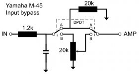
I'm thinking of putting in a bypass switch on the rear for direct input
connection vs. pot volume control. No harder than permanent bias AB from Step 4. Make sure you study the schematic so you don't
bypass a critical circuit. The wiper at max ohms is a short to
ground (mute) while the wiper at close to 0 ohms is a near bypass
of the pot.
The input is a resistor to pot and cap to ground. . .after the pot. .
the input resistors and caps before the LTP.
Step 7)
For a good time. . . good warmup exercise.
Step 8)
I perish the thought. . .$$$. There are some pricey caps in this
amp. . .but replace what you can. . .
Step 9)
Yes.
Step 10)
Use the lightbulb trick to low power on the amp. . .smell and look
for glowing parts. . .
Step 1)
Yes.
Step 2)
That's a big process.
Step 3)
Yes.
Step 4)
Yes. This is a good move.
Step 5)
There are some warnings about multiturn pots: smaller contact
area = possibility of current killing the contact and making the
bias less precise - this was pointed out by anatech. . . above
in fact.
10mV across 0.22ohms = 45.455mA
11mV across 0.22ohms = 50.0mA--[+0.83 dB]
12mV across 0.22ohms = 54.5mA--[+1.57 dB]
13mV across 0.22ohms = 59.1mA--[+2.28 dB]
14mV across 0.22ohms = 63.6mA--[+2.92 dB]
15mV across 0.22ohms = 68.2mA--[+3.52 dB]
Step 6)
I'm thinking of putting in a bypass switch on the rear for direct input
connection vs. pot volume control. No harder than permanent bias AB from Step 4. Make sure you study the schematic so you don't
bypass a critical circuit. The wiper at max ohms is a short to
ground (mute) while the wiper at close to 0 ohms is a near bypass
of the pot.
The input is a resistor to pot and cap to ground. . .after the pot. .
the input resistors and caps before the LTP.
Step 7)
For a good time. . . good warmup exercise.
Step 8)
I perish the thought. . .$$$. There are some pricey caps in this
amp. . .but replace what you can. . .
Step 9)
Yes.
Step 10)
Use the lightbulb trick to low power on the amp. . .smell and look
for glowing parts. . .
anatech said:What did you do with them? Never heard of these things quitting permanently.
Still have them, no they're not for sale, just secondary on my list of things to repair.
anatech said:That stuff didn't sound as good as you think. Consider yourself lucky that you were not wealthy!
Just a difference of opinion here, FYI for many years the B&W 801f's were used as studio monitors in many recording studios, especially those that recorded digitally. Many people still consider them legendary. Of course you have to keep in mind that speaker preference is subjective.
Originally posted by gni
Use the lightbulb trick to low power on the amp. . .smell and look
for glowing parts. . .
Are you referring to a Variable AC transformer?
Just a 70W light bulb in series with the AC mains. . .good indicator
of current draw. . .limits since as more current is drawn. . .the
bulb resistance goes up. . .limiting the overall voltage at the
amplifier.
Cheaper than variable transformer. . .
Need two DPDT switches--one for left and one for right: if mounted on
back the input wiring will be longer.
of current draw. . .limits since as more current is drawn. . .the
bulb resistance goes up. . .limiting the overall voltage at the
amplifier.
Cheaper than variable transformer. . .
Need two DPDT switches--one for left and one for right: if mounted on
back the input wiring will be longer.
anatech said:Hi Joe,
Sorry bluesmoke
This is a risky move guys. The wiper on these is not intended to pass current. Stay with a 270 ° type. The parts inside a multiturn control are much finer than a standard type. If you don't believe me, then take one apart and see for yourself..
No!
No! It won't buy you anything!
-Chris
No worries.
re: Bias pot. Understandable, and I agree 99%. With the M80 being quite touchy, there is a lot more control with the multiturn to get both channels even (remember to tap it when finished, and then re-measure). As for current handling, I'd trust a single turn. (~I'm learning; though no problems so far) Just wondering why quite a few mid-level amps I've seen use the multi-turns for bias (like my old Aragon). Haven't been able to peek into amps that cost more than a car yet... Would have to buy drool insurance....
re: Bypass the input pots. Why not? (real question) When I want to test, I use ground-shunted rca plugs on the input to mute, or use an external volume control (passive).
re: Replace power cord. Although not an advantage electronically, it can just look better, be a more durable type, even a correctly rated modular socket could be nice. Just a matter of preference. Make it your own! Won't hurt any!
Bypass input pots:
just need to replace the same resistance to ground that the
input pot presented in the circuit.
Bypass input pots with switch:
. . .tricky I just realized. . .any switch noise will go on to be
amplified at full scale. Ouch!
The whole bias problem:
Multi-Turn or Single-Turn!
Multi-turn are said to not be made for DC current.
Single-Turn are said to handle more power.
In the end. . .as DIYers. . .we are going to tweak again and again. . .
so. . . In my opinion, the multi-turn will work since the amount of
current going through it is so small. . . microamps and we are going
to tweak next week. . .and the week after. . . and the month after. . etc.
- Status
- This old topic is closed. If you want to reopen this topic, contact a moderator using the "Report Post" button.
- Home
- Amplifiers
- Solid State
- Yamaha M-80 Mods FINISHED! GOLD!!!