Hi,
Stuart is right and supports Kamps. I cannot disagree that Iq=2.76A gives MORE than 100W of ClassA into 8r.
I think we are also agreed that KSA100mk2 will safely deliver a lot more than 100W into 8r. Mark has stated 160W.
I also will not/cannot dispute Kamps measurements and calculations leading to
On the same basis that both the KSA50mk2 and our 50 Klone will push a lot more than 50W into 8r does not stop us specifying an Iq=1.9A giving about 58W ClassA for an amp capable of a maximum of about 70W to 80W.
I think we are all agreed that our 50 Klone is fully biased to ClassA just as a Klone of the 100Mk2 biased to 2.76A will be fully biased to ClassA. These levels of bias separate the Klone and their originals from the high bias designs that CLAIM to be ClassA. Keep in mind that a less than scrupulous retailer could under specify the output power of a high bias amp and then rightly (or wrongly depending on the method of measurement) claim they had a ClassA design. I believe that neither Krell nor the Klone builders need to resort to this style of chicanery.
From some of the information I have seen the 100Mk1 was a high bias design. That distinction was the main purpose of my original statement.
But, I thank Kamps again for the info, it gets the designers/builders closer to specifying the Klone requirements.
Stuart is right and supports Kamps. I cannot disagree that Iq=2.76A gives MORE than 100W of ClassA into 8r.
I think we are also agreed that KSA100mk2 will safely deliver a lot more than 100W into 8r. Mark has stated 160W.
I also will not/cannot dispute Kamps measurements and calculations leading to
690mv across the 1 ohm emitter resistors meant it was biased to 122 watts pure class-A into 8 ohms
On the same basis that both the KSA50mk2 and our 50 Klone will push a lot more than 50W into 8r does not stop us specifying an Iq=1.9A giving about 58W ClassA for an amp capable of a maximum of about 70W to 80W.
I think we are all agreed that our 50 Klone is fully biased to ClassA just as a Klone of the 100Mk2 biased to 2.76A will be fully biased to ClassA. These levels of bias separate the Klone and their originals from the high bias designs that CLAIM to be ClassA. Keep in mind that a less than scrupulous retailer could under specify the output power of a high bias amp and then rightly (or wrongly depending on the method of measurement) claim they had a ClassA design. I believe that neither Krell nor the Klone builders need to resort to this style of chicanery.
From some of the information I have seen the 100Mk1 was a high bias design. That distinction was the main purpose of my original statement.
But, I thank Kamps again for the info, it gets the designers/builders closer to specifying the Klone requirements.
AndrewT said:Hi Kamps,
not quite, your measured Vrail supports the contention of Mark that the peak output of the 100Mk2 is nearer 160W (50.6Vpk) into 8r.
0.69V bias gives Iq=2.76A.
Peak voltage in ClassA will be just below 2*2.76*8= 44.16Vpk.
I would expect the KSA100mk2 to manage quite a bit than 44.1Vpk into 8r.
ps what is the rated input voltage for the rated (specification) output voltage?
44.16v peak is about 31.2v RMS class-A or 31.2 X 31.2 /8 = 121.5 watts RMS pure class-A. Supports the previous.
Also the 160 watt figure seems to be the class AB max output prior to clipping, not pure class-A max (which at Iq of 2.76A is limited to 122 watts into 8 ohms).
Stuart is right, my calculations were based on a purely resistive load.
Thank you all for helping clarify this.
Am finally back after a long winded service trip through Nevada. Nothing is close together in that state!
Many have asked or denied they need to build the larger Krell....however......
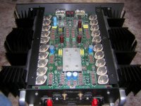
Yesterday we had the opportunity to compare my KSA-50 MK-2 Klone to Bill WW's Krell KST-100 Class A-B amp. Clearly the KSA-50 clobbered the KST-100 in high frequency end of things... it was much more refined while the Krell KST was colder fomr about 5K up and just a tad bit gritty sounding. HOWEVER... the KST-100 blew the KSA-50 out of the water in the low end department driving my Dynaudios with a slam factor that never seemed to run out. The KST was literally able to make my floors shake playing back track 1 from Crystal Method, clearly the KST was definately more like my old KSA-80B. Also the KST-100 was not lagging that far behind in the midrange department as compared to the KSA-50, it was close with the KSA-50 taking the edge. The KSA-50 MK-2 kas really amazing bass response for a 50 watt amp but is nothing compared to the KST-100! This only re-affirms to me that the KSA-100MK-2 is the next thing on my list to build. Clearly my Dynaudios and a larger Krell are a much better match and I will continue to go ahead with the KSA-100 MK-2 amp.
Those of you that have speakers in the 86 to 90db sensitivity range also really need a larger amp to get the results I have been able to get with the larger Krells.
The KST looks like a pretty complicated circuit to attempt to Klone and I don't think it would be worthwhile to do. At that point going to the KSA-80 would be the better route to take for the time and $$ involved. Here is a photo of the inside of the KST.
Mark
Many have asked or denied they need to build the larger Krell....however......
Yesterday we had the opportunity to compare my KSA-50 MK-2 Klone to Bill WW's Krell KST-100 Class A-B amp. Clearly the KSA-50 clobbered the KST-100 in high frequency end of things... it was much more refined while the Krell KST was colder fomr about 5K up and just a tad bit gritty sounding. HOWEVER... the KST-100 blew the KSA-50 out of the water in the low end department driving my Dynaudios with a slam factor that never seemed to run out. The KST was literally able to make my floors shake playing back track 1 from Crystal Method, clearly the KST was definately more like my old KSA-80B. Also the KST-100 was not lagging that far behind in the midrange department as compared to the KSA-50, it was close with the KSA-50 taking the edge. The KSA-50 MK-2 kas really amazing bass response for a 50 watt amp but is nothing compared to the KST-100! This only re-affirms to me that the KSA-100MK-2 is the next thing on my list to build. Clearly my Dynaudios and a larger Krell are a much better match and I will continue to go ahead with the KSA-100 MK-2 amp.
Those of you that have speakers in the 86 to 90db sensitivity range also really need a larger amp to get the results I have been able to get with the larger Krells.
The KST looks like a pretty complicated circuit to attempt to Klone and I don't think it would be worthwhile to do. At that point going to the KSA-80 would be the better route to take for the time and $$ involved. Here is a photo of the inside of the KST.
Mark
Attachments
Hi Mark
I liked that, and I am very interested to join this project.
BTW, interesting picture, every component placed on one board (it looks like that). If building an amp like the one on the pictures it demands a chassis that fits perfect for the board, dont you think?
It must be easier to build an amp (clone?) where you could have different options for to choose the chassis you like ( or maybe already have) ?
The project must go for one main/driver board per channel. thats only my opinion.
Regards
This only re-affirms to me that the KSA-100MK-2 is the next thing on my list to build. Clearly my Dynaudios and a larger Krell are a much better match and I will continue to go ahead with the KSA-100 MK-2 amp.
I liked that, and I am very interested to join this project.
BTW, interesting picture, every component placed on one board (it looks like that). If building an amp like the one on the pictures it demands a chassis that fits perfect for the board, dont you think?
It must be easier to build an amp (clone?) where you could have different options for to choose the chassis you like ( or maybe already have) ?
The project must go for one main/driver board per channel. thats only my opinion.
Regards
Hi PWatts
Are you going to design a PCB for the KSA 100mkII clone?
If yes, im wery interested to joining in and help if I can.
Also, I must admit that the long delay between posts in this thread had lead me to design a PCB on my own software. PCB design is not finished, only component placing and outer physical format of the board is done. No routing of traces and no ground-plane is done yet. (board outline ca 5.50" x 5.00").
I dont know if this could be of interest or you would like to start from scratch(or maybe you already have started).
BTW, right now Im searching for computer grade caps for this project( see this thread: http://www.diyaudio.com/forums/showthread.php?s=&postid=1011227#post1011227 )
Regards
Hi Flod,
Or, are you just jumping on a fad, used by others that have never reviewed the need, for an audio amplifier ground plane?
Is that a power ground plane, or a signal (clean) ground plane, or a zero current electrostatic screen ground plane? Have you considered when a ground plane might be useful? Do any of the pros apply to audio amplifiers? Do any of the cons work against audio amplifiers?no ground-plane is done yet
Or, are you just jumping on a fad, used by others that have never reviewed the need, for an audio amplifier ground plane?
I haven't done any work yet on the board, but since there seems to be a lot of interest on a KSA100 clone and as I think that Al has made more than his share of contributions, somebody else might take it further.
There's no need to do a completely new design since his KSA50 boards are well designed and also work well. The same general layout could be used as basis; otherwise the genuine KSA100 MK2 board can simply be copied and adapted for the modern components.
I'd suggest that all the comments of what should be included on this clone compared to the KSA50 should come in within the next two weeks or so, after which design can start. Component identification should be one of the first choices, especially the MOSFET's. The BJT's can stay the same as with the KSA50. The protection, fan controllers etc. are all off-board and not part of the board itself.
It will be too expensive to start a group buy from South Africa since all the boards will have to be sent overseas, so I'd suggest that someone abroad with access to a PCB manufacturing facility handle that part, supplied with the Gerbers.
AndrewT raises a very important point, often (OK usually) overlooked by many designers, both DIY and professional. Grounding principles on a PCB is a very touchy subject for some, and opinions vary on what works best. Particularly in a mixed-signal environment there are a plethora of ideas and methods used, some with disastrous results.
The fact of the matter is that just by doing lots of copper pours, dedicated ground plane on a multilayer board or exotic copper plate shielding or similar can lead to worse performance than a much simpler well-designed ground scheme.
For a power amplifier ground and power planes are largely unnecessary. Proper care needs to be taken to prevent signal ground as the return for power ground, and to a certain extent screening of the signal ground should work well. A dedicated ground or power plane for power isn't really necessary, but will reduce DC resistance that may be a problem. Thick traces are sufficient for even very demanding amps though and a plane is overkill. The reason why power and ground planes are popular is due to digital electronics where the small inductance of the trace DO make a difference at high frequencies that are not the case here. A dedicated ground plane in a multilayer board is also used as a screen between the top and bottom layers to prevent signal coupling through the board substrate.
For normal non-switching amplifiers a double-sided board is more than sufficient as most of the advantages mentioned are not applicable. A properly designed copper pour for signal ground is unlikely to do any harm though, but a dedicated ground plane on an expensive 4-layer board is definitely overkill, and can even count against you.
it's a fact that KSA 50 and lookalikes are more than classics in last few decades
one example of this is Oly's bipamp- (Oly is Vangelis here at DIY) ,and he constructed it several years ago; I can't describe his reaction when I send him KSA schematics (somewhere in KSA thread beginning) -he was really surprised how his amp is almost same as KSA.....with few differences ,regarding fewer outputs etc.....
this is one of iterations of pcb for his amp-there you can see his mileage in making demanding pcb applications-this pcb look so simple....but I know that I can't make anything like this....
Attachments
I'm definately interested still but lack of time due to lots of work has kept me at bay onthis project. I would front the $$ to get a batch of boards made up from someone's cad work that we can all agree on as I did on the KSA-50 klone. Please make this the MK-2 version as building the earlier versions on the same board will also then be possible ust by adding eom jumpers at unneeded parts locations. Also no planes of any type please... makes parts removal a pain in the butt! Planes are a big fad IMHO.... Not necessary except in RF equipment.
Mark
Mark
Any suggestions so far for the MOSFET's? Preferably something easily available for people all over the world, so if it could be from ONSemi or so it would be great.
As to the layout, I've thought of replicating the original KSA100 Mk2's board in terms of the connector locations, board dimensions and mounting holes. Not only for nostalgic purposes, but also to make it easy to swop around for people with original KSA100's who'd like to do an easy upgrade instead of modding the old boards.
The only issue will be the driver heatsinks - the boltdown type's not going to work as it's going to be too hard for everybody to find the same heatsink. Unfortunately I know from experience that that heatsink on the original KSA100 gets DAMN hot, so it cannot be skimped upon.
I did a few SPice simulations, and fortunately a few adaptions can easily be made without any penalty. The component variation is actually less than on the KSA50, and all the resistors can be 0.25W except R11-R14 which has to be 0.5W. The output stage's emitter resistors have to be 5W naturally.
Pretty much the same rules as for the KSA50 applies wrt to component tolerance, capacitor quality etc. To stay close to the original, the 62pF caps should be silver mica, and the input shunt an MKP. Polystyrene/polypropylene is a worthy substitution for both, but proper COG ceramics will do fine too. Elna Cerafines will be a good choice for the feedback electrolytic, otherwise a Black Gate NX. For the power supply decoupling Panasonic FC's would be good.
Only the differential amp transistors and zeners should ideally be matched; the rest should be OK without matching.
The following semiconductor substitutions can be made:
Q1,Q2: MPSA42
Q3,Q4: MPSA92
Q5,Q6: IRF610
Q7,Q8: IRF9610
Q9,Q11,Q15,Q17: MJE15031
Q10,Q12,Q13,Q14,Q16: MJE15031
Outputs: MJ(L)21194/3; MJL3281/1302, MJL4281/4302 or any of the popular Sanken or Toshiba types already discussed.
The only part that will be a bit difficult to source is the 1N5309 current regulator. The Vishay CR300 and J509 are viable alternatives, but none of these are easily available. Just to get it working, an 8k2 resistor should do the job, otherwise a JFET can be used. A proper current regulator IC can be used that will also improve performance marginally, but will take up board space. I would suggest that whoever organise the group buy (Mark A?) order a lot of these regulators from Mouser or DigiKey and provide them along with the boards.
A group buy of the resistors and capacitors is a good idea to keep costs down and avoid everybody from placing a special order for only one component.
The trimpots, zeners, transistors, emitter resistors, driver heatsinks, electrolytics etc. are each to his own, but I'd suggest to provide the following as default part of the group buy:
1) All small-signal resistors: Dale
2) 62pF & 680pF caps: silver mica
3) 100nF: Wima MKP
These parts in total will be in the region of $25 for two channels' worth.
Hi,
having suggested the adoption of the far faster and more linear and higher gain output devices, I think you should ditch the thought of using mpsa42/92 for the LTP.
A similar upgrade as that applied to the output end would seem more appropriate.
My votes go to
bc546/556b or preferably c grade.
or
2n5551/5401
or
2sa872/c1775, this last probably being best from these three.
Would the locations using MJE15031 benefit from using the slightly better 15034/5? Or something much faster and higher gain.
Mouser has them
here Quantitiy purcahses don't drop the price very much on these devices.... but I could supply these and the mosfets with the boards. I also have a good working Tektronix 575 curve tracer if we want to match input devices.
I assume you're taling about the MK-2 version of the KSA-100... I don't have the diagrams handy here at work.... With the MK-2 version there is also the need for the mosfets and I had foind a sutable sub for those too. IRF 610 and 9610 will work but these devices are run at extremely low curent and I believe a smaller-higher quality device can safely be used in these positions. Can you check this on your spice program.....?
Mark
AndrewT said:something much faster and higher gain.
Go nuts in combination with the MJL4302/MJL4281:
2SA1860/2SC4886
Or go completely insane: 2SA1141/2SC2681
(For some obscure reason these are less than $1.50 overhere)
Yes I am referring to the Mk2.
I have no qualms of using different transistors for the drivers, Mosfets etc, but I was thinking along the lines of what is easily available. MJE1503x and IRFx10 devices are easy and relatively cheap to buy, even at lowly electronics shops. 2Sx transistors and different mosfets are harder to find though, especially in Dark Africa. Going with ONSemi heaven is at hand for only $21
I agree that BC546/556 and the others may be better suited - what about MPS8099/8599?
However, since the stability margin of the KSA is very large, anybody can basically use whatever he/she wants since the package of everything is likely to remain TO220. Likewise switching between TO92 input transistors is also easy.
MJE15034/5 is a perhaps a good idea, I'm already using them in my KSA50 clone. Whether they really perform (audible/measurable) better is debatable.
The original FET's used was spec'd at 100V 3A 2ohms. The IRF610/9610 is easily available but is indeed perhaps not as well suited to a low current duty. A very interesting FET alternative is the IRFD110/9110. These use a nice and small package, and are rated at 100V, 1A, 0.54ohm. They're similarly priced to IRF610, but I don't know how easy they are to get, and their package means that you're stuck with them. Anybody have any suggestions for a better choice available in TO220?
Concerning features I don't think there's much more to add that Al hasn't already incorporated in his boards, any suggestions?
Even though Mouser has the current sources available cheaply, the problem lies with shipping, especially for those overseas. Including components such as these with the board will make it far easier and cheaper for builders.
- Home
- Amplifiers
- Solid State
- Krell KSA 100mkII Clone