I fried some parts on my Julia sound card ( with180 volts dc !).
It looks like a transistor is blown open and a resistor is open ckt.
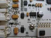
Left channel , output section.
The transistor has a marking MAX D7 ( Q5). The blown resistor (R130) seems to be 100 ohms . The Right channel is fine. Can't say if the 47uF /16V cap (C72) is dead ( seems to be OK ) and the JRC 4580 opamp (U23).
The high voltage was momentary as a loose output cable brushed past the pcb with 180 volts on it. There was an audible bang from the inside of my computer case.
I think the balanced section of the card might work.
Any idea what the transistor is and where I can get one? It looks like it is being used to mute the output.
Thanks for any help.
Cheers,
Ashok.
It looks like a transistor is blown open and a resistor is open ckt.
Left channel , output section.
The transistor has a marking MAX D7 ( Q5). The blown resistor (R130) seems to be 100 ohms . The Right channel is fine. Can't say if the 47uF /16V cap (C72) is dead ( seems to be OK ) and the JRC 4580 opamp (U23).
The high voltage was momentary as a loose output cable brushed past the pcb with 180 volts on it. There was an audible bang from the inside of my computer case.
I think the balanced section of the card might work.
Any idea what the transistor is and where I can get one? It looks like it is being used to mute the output.
Thanks for any help.
Cheers,
Ashok.
I changed the damaged resistor and removed the ( mute?) transistor. The channel still does not work. Neither does the balanced input side on the same channel. So something common to both ends of the board .
Wonder if anyone knows what could be blown. The inputs are all OK.
Schematic or block diagram anyone ?
Thanks.
Cheers,
Ashok.
Wonder if anyone knows what could be blown. The inputs are all OK.
Schematic or block diagram anyone ?
Thanks.
Cheers,
Ashok.
Hi ashok,
Two things to check. One, have a good look at the card for blown ground or supply traces. Two, run the card in the computer where you can get to it. Finger test for hot chips. Watch out, you can leave skin behind if you aren't careful.
Sorry to hear about that happening to you. It just might be new card time.
-Chris
That sounds like high energy went into places where you don't want it.There was an audible bang from the inside of my computer case.
Two things to check. One, have a good look at the card for blown ground or supply traces. Two, run the card in the computer where you can get to it. Finger test for hot chips. Watch out, you can leave skin behind if you aren't careful.
Sorry to hear about that happening to you. It just might be new card time.
-Chris
anatech said:It just might be new card time.
-Chris
 A new Julia ? Others buy a used car for that... (An old one)
Maybe the opamp is blown (very likely). Let's hope not more...
Mike
Hi Mike,
I am not familiar to the "Julia". My comment was towards replacing it with *something*.
Hi Eva,
Normally you are right, but the damage could be worse. I look at this as being similar to a lightening hit. In seeking ground, the 180 V could have blown grounds, then travelled through the 5 V rails or 12 V rails to ground. This can take out everything in sight, even past the cracked or smoked IC's and one level back.
I hope this is not the case.
-Chris
Sounds like to be that one: http://www.digit-life.com/articles2/esi-julia/index.html
As the other channel is still functional it's likely to be a smaller defect ?
Mike
As the other channel is still functional it's likely to be a smaller defect ?
Mike
The block diagram may provide some hints:
http://www.ixbt.com/multimedia/esi/julia/scheme-big.png
The grey stuff between the DAC and the output buffer is what I called analog mixer. It's probably one of the ICs of the big PCB, altough it could be located in the smaller one instead. You should find out which one, get its datasheet to know the pinout, and check that it's actually outputing signal through both channels. If it's ok, then the problem comes from the output buffer.
Also, you may try reversing the big PCB in order to test whether the other set of inputs/outputs works properly or not.
Thanks Guys,
I appreciate all the help. Buying another Julia is not an attractive option at all !
I did turn around the card and checked the balanced outputs. Same result. All inputs OK , Right channel output OK .
Left channel output still dead .
Since the opamps on the balanced side might be OK (?) it could be the mixer chip as suggested by Eva.
I'll try to check the DAC outputs using a scope later on , if the mixer test fails or I can't figure out how to do it.
It just occured to me to check the power supplies for the opamps.
Since I have one good channel, I can compare voltages.
I guess Iwill have to contact ESI in any case.
Any additional help will be useful.
Jackinnj -- Thanks for that suggestion. I think I will try and get some of those opto couplers.
Thanks.
Ashok.
Careful, analog optoisolators tend to have rather high distortion... I particulairly dislike the PC having it's chasis and all grounds connected to the mains earth line, lots of ground loop and 50/60Hz induction problems with that. I was thinking about buying an USB sound card and inserting galvanic isolation between the ADC/DAC digital IOs and the USB chip, using something like an ADUMxxx isolator. Also, isolated DAC/ADC power supply using a DC-DC converter module. So many projects, so little time 
Hi Ashok,
I happen to have a ESI Juli@ card, is there anything a can check up on my card, or perhaps take a close-up pic for you that would help you out a bit?
Cheers Michael
EDIT PS: I f anyone get's a hold on a schematic on that soundcard I would be glad to receive a copy as I would like to tweak it!
I happen to have a ESI Juli@ card, is there anything a can check up on my card, or perhaps take a close-up pic for you that would help you out a bit?
Cheers Michael
EDIT PS: I f anyone get's a hold on a schematic on that soundcard I would be glad to receive a copy as I would like to tweak it!
ilimzn said:Careful, analog optoisolators tend to have rather high distortion...
the simple diode/photoresistor types are non-linear and slow, some of the Siemens are good for several hundred kHz with high linearity -- these have one emitter and two photo-receptors, one of which is hooked up as a servo -- i haven't checked for harmonic distortion, although it wouldn't seem to be a problem -- I will test and let you know, however. Could be that the junction capacitance wasn't dealt with. The analog opto-isolators are most easily deployed in uni-polar applications so a blocking cap is necessary for music. bipolar operations are tricky and there's bound to be some crossover error.
it's fortunate that only a sound-card was involved -- if you had an indavertent application of hv on a laptop you can kiss the entire sucker goodbye.
Schematic
This isn't quite the right place to ask, but does anyone happen to have a schematic for the ESI Juli?
I'm looking to make a PC scope (I'm trying to get a cheap lab at home) and would like to know a few things like:
Is the Juli DC-coupled? (optimistic I know)
What is the fixed, analogue low-pass filter like? (order, -3dB point, etc)
I tried asking ESI (uk) and the support guy told me he'd email me a schematic, but seems to have forgotten (or neglected to bother...)
I ask as a schematic will make your fault-finding an easier job - like finding your way round a room with a blown bulb after knowing where everything is to begin with!
Good luck on the soundcard fix
OK I'm back with the Juli@ card . I want to fix it !
Later I could put it in a computer from where I could access it via soldered lead out wires. That will take time so a picture and some questions.
1. Does anyone have a circuit diagram ?
2. Notice the smallest NJM4580 chip I could find ( on the connector J6 ) It's still very much larger than the U23 chip which I want to replace. Any sources for the small chip ?
3. I can't see any burnt traces.
4. I removed the Q5 transistor which was blown ( physically )
5. Would the caps in that area also be blown. They don't measure as a short.
6. Is the transistor Q5 in parallel with the output ? That would mean it doesn't matter if it is not there except for switching noises.
7. R103 is VERY poorly soldered by me. I'll change it later. It also appears to be a wrong value.
8. Note that the good channel works normally , both input and output. Blown channel input also works. Only output is damaged.
9. Is the balanced output derived from the unbalanced output opamp?
Anyone any suggestions ?
Thanks.
Ashok.
Attachments

- Status
- This old topic is closed. If you want to reopen this topic, contact a moderator using the "Report Post" button.
- Home
- Amplifiers
- Solid State
- SMD parts on Julia sound card blown.