There are several alternatives:
- LM338 is rated at 5A and is very easy to use, like the LM317.
- The LM317 may be current-boosted by adding an external pass transistor. The datasheet shows how to do it, I think.
- A discrete regulator may be considered. There are already plenty of schematics published in internet and in this forum, so all what you have to do is search.
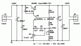
Eva said:Are you aware that any minor input voltage increase will blow Q2 (limited to 500mA and 0.625W) and Q3 (limited to 100mA) ?
Yes you must set the right value for R4, i use Iq ~46mA, with Q1 ~80 hfe
.
It's easy to calculate:
Ib (Q1) = Itotal / hfe (Q1) = 2A / 80 = 0,025A
Iq = Ib + I_Q3 = 0,025A + 0,021 A
Vdiff = Vinput - Voutput - 1V (Q1 ECsat) = 65V -57V -1V = 7V
R4 = Vdiff / Iq = 7 / 0,046 = 152 Ohm
In these circumstances, with no load, Q2 would be conducting 46mA while whitstandings 45V between C and E, so it would be dissipating more than 2 watts and would porbably blow after a few seconds.
There are other ways to get such a circuit to work properly, for example, by adding a PNP gain stage with its emitter connected to the input, its base driven with Q2 and its collector driving the base of Q1. It would make frequency stabilisation harder due to the additional pole, though.
There are other ways to get such a circuit to work properly, for example, by adding a PNP gain stage with its emitter connected to the input, its base driven with Q2 and its collector driving the base of Q1. It would make frequency stabilisation harder due to the additional pole, though.
Hello Eva,
Yes you are right, Q2 as to less Power.
I thing more current Gain for Q1 like a Darlington NPN Transistor solve the work.
And with Iq ~ 3mA it ok ?
Eva said:In these circumstances, with no load, Q2 would be conducting 46mA while whitstandings 45V between C and E, so it would be dissipating more than 2 watts and would porbably blow after a few seconds.
Yes you are right, Q2 as to less Power.
I thing more current Gain for Q1 like a Darlington NPN Transistor solve the work.
And with Iq ~ 3mA it ok ?
Attachments
- Status
- This old topic is closed. If you want to reopen this topic, contact a moderator using the "Report Post" button.
- Home
- Amplifiers
- Solid State
- 57 V regulated low noise