I am working on a preamplifier project based on a simple circuit powered by a +/- power supply.
The principle for wiring the ground wires is shown as attached. Signal path is blue. The signal wire from output at the PCB to the output RCA socket is not shielded because the distance is ultra short.
All RCA socket sleeves are connected and from a single point at the connecting wire there is contact to the enclosure.
If I connect the shield of the input signal wire going to the potmeter with the shield of the output signal wire from the pot (red) there is a weak hum. This disappears completely if this shield connection is cut (yellow line).
So I suspect I have found the optimal grounding scheeme, or is there another way that will be hum free and make the circuit sound as good as possible?
Before trying all possible combinations in a trial and error procedure I want to hear your opinions.
Attachments
Yes, you have found a good grounding.
If you connect the shield at the pot,
you will get two different ground rails,
that goes between the input jack and amplifier central ground point.
Thid is called a ground loop. And this can be a trouble. (with hum)
Compare a race track for cars. It is a loop.
And to come from half way of track back to start
you can go two ways.
In an amplifier it is not good if same current can use two different roads back to zero, ground.
If pot is far from PCB, you should keep that second part of shielding.
If you have potentiometer close to OP-amp
you can remove that little other shielding part.
You replace ground from pot to Op-amp with a thin wire or a PCB track.
For potentiometers this method of getting close can mean
you will have use a long shaft connected between front panel and pot axis.
Or you can put potentiometer in front panel, and have PCB sitting very close to pot ( on the pot pins ).
pinkmouse said:If it works, then you are quite entitled to leave it well alone!
But, if it were me, I would reinstate the yellow wire, and cut the screen where it joins the PCB. It just keeps a little extra noise off the PCB.
Thank you pinkmouse!
Will it from a theoretical point of view be good to take the ground wire from the PCB via the PSU minus to RCA sleeves and enclosure ground or let the minus lead, as in my first suggestion, be a "dead end" to the PSU (see attachment)

Attachments
Another option often used
is to use input RCA jacks isolated from case.
RCA jacks with plastic isolation bricks can be expensive.
I use normal RCA inputs without isolation.
I make a hole in case that is bigger than both RCA.
Then I take a bit of hard plastic sheet 1.5mm thick and screw it on the inside of case to cover this hole.
In this 'isolation plastic' I have 2 drilled holes for RCA.
This way there is no ground connection from RCA input to case.
The ground for each input, goes in shielded cable
to amplifier input (or potentiometer ground).
lineup said:Another option often used
is to use input RCA jacks isolated from case.
RCA jacks with plastic isolation bricks can be expensive.
I use normal RCA inputs without isolation.
I make a hole in case that is bigger than both RCA.
Then I take a bit of hard plastic sheet 1.5mm thick and screw it on the inside of case to cover this hole.
In this 'isolation plastic' I have 2 drilled holes for RCA.
This way there is no ground connection from RCA input to case.
The ground for each input, goes in shielded cable
to amplifier input (or potentiometer ground).
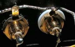
The RCA sockets in my project are all but one isolated from the enclosure. The sleeves of all the jacks are connected by a wire that goes from sleeve to sleeve. One single RCA jack is without isolation and forms the single enclosure ground point, see picture.
The wire connecting all the jack-sleeves currently goes to the common PCB ground point. My last question was whether this wire should go to the PSU minus pole before going to the common PCB ground point, OR go from the jack-sleeves directly to the common PCB ground point and then onwards to the PSU minus pole as a "dead end"?
Attachments
lineup said:Another option often used
is to use input RCA jacks isolated from case.
RCA jacks with plastic isolation bricks can be expensive.
I use normal RCA inputs without isolation.
There are fairly cheap insulated and gold plated ones too, if one can only find the right place to buy them. There is what seems to be a generic type that is sold around the world, but prices vary. Here in Sweden I can buy a pair of two for less than 3 € at BilTema, while Elfa used to sell them for about twice that price for a single one. BilTema seems only to have two stores in Denmark (Aalborg and Naestved), but I am sure there are other companies selling them too. I have seen exactly tha same type on many photos of equipment on this forum from around the world.
http://www.biltema.se/products/product.asp?iItemId=78714
Hm, and now when I checked them up to provide the link, I see they now look a little bit different from the ones I have bought earlier, but they are still isolated and gold-plated.
pinkmouse said:Common ground first.
Sorry, I suffer from a cold that may block my ability to understand. Could you explain what you mean?
Christer said:
There are fairly cheap insulated and gold plated ones too, if one can only find the right place to buy them. There is what seems to be a generic type that is sold around the world, but prices vary. Here in Sweden I can buy a pair of two for less than 3 € at BilTema, while Elfa used to sell them for about twice that price for a single one. BilTema seems only to have two stores in Denmark (Aalborg and Naestved), but I am sure there are other companies selling them too. I have seen exactly tha same type on many photos of equipment on this forum from around the world.
http://www.biltema.se/products/product.asp?iItemId=78714
Hm, and now when I checked them up to provide the link, I see they now look a little bit different from the ones I have bought earlier, but they are still isolated and gold-plated.
Correct, this type is for sale everywhere. But beware! Most of them do not have a fixed center pin. It rotates with the RCA plug you may rotate to get it in or out, and imagine what happens to the wire soldered at the inside og the enclosure.
So before you buy make sure they have a fixed center pin!

klitgt said:The RCA sockets in my project are all but one isolated from the enclosure.
My last question was whether this wire should go to the PSU minus pole before going to the common PCB ground point, OR go from the jack-sleeves directly to the common PCB ground point and then onwards to the PSU minus pole as a "dead end"?
Most used solution is separate pin at amp input at PCB.
At this is connected.:
input signal ground+potentiometer ground+amp input resistor ground
From this ground goes a track to PCB common ground = power supply ground connection.
-------
To make connection to PCB common ground is possible, too.
And, not often but sometimes, making all ground connections directly to power supply capacitors negative is used.
You said:
Then I said:
Make sense now?
In your terminology, all ground runs should be "dead ends" where possible.
klitgt said:...OR go from the jack-sleeves directly to the common PCB ground point and then onwards to the PSU minus pole as a "dead end"?
Then I said:
pinkmouse said:Common ground first.
Make sense now?
In your terminology, all ground runs should be "dead ends" where possible.
lineup said:
Most used solution is separate pin at amp input at PCB.
At this is connected.:
input signal ground+potentiometer ground+amp input resistor ground
From this ground goes a track to PCB common ground = power supply ground connection.
Hi lineup, just one thing that may confuse you (and others): I run a +/- PSU, not a +/0/- PSU, the latter always has 0 as ground. My PSU has - (minus) going to ground.
pinkmouse said:You said:
Then I said:
Make sense now?
In your terminology, all ground runs should be "dead ends" where possible.
Thank you, now I understand everything perfectly!

Christer said:Hm, and now when I checked them up to provide the link, I see they now look a little bit different from the ones I have bought earlier, but they are still isolated and gold-plated.
I have no idea why they are using that picture since they are still selling the version with white washers(I presume that's what you were refering to). Have got quite a lot of those in my bin. Somehow I doubt they are good sound though...
Lovan said:
I have no idea why they are using that picture since they are still selling the version with white washers(I presume that's what you were refering to). Have got quite a lot of those in my bin. Somehow I doubt they are good sound though...
White washsers, yes, that's the ones I was referring to, and I am also quite sure i had a look in those shelves and saw them as late as just a few days before Christmas. As far as I can tell they are identical to the ones Elfa used to have at a much higher price. They are hardly very high quality, considering the low price, and that they seem to show up here and there, all over the world, usually relabelled with the brand of the company selling them.
- Status
- This old topic is closed. If you want to reopen this topic, contact a moderator using the "Report Post" button.
- Home
- Amplifiers
- Solid State
- Optimal grounding scheeme