when you look
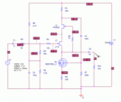
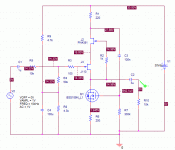
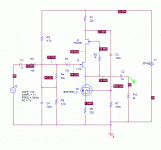
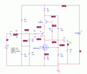
at my schematic of this 'version 2c'
you may wonder:
what are the optimal values for R5, R6 and C2?
Actually they were all
chosen to give best performance at normal levels of output.
This version is intended to put out 1-2 Volt into loads of 2.2 - 10 kohm.
I can mention, at this voltage supply +/-15 Volt
the optimal value for R5 (10kohm) is 9.1kohm ....!!!!
8.2 or 10 kohm gives a tiny bit more distortion.
But as the difference is very very small I prefer to recommend R5 = 10 kOhm.
10 kohm resistors is easy to find and good to have at home. Like 1 kohm resistors!
R5 = 10000 Ohm will give 2.8 mA in RED LED reference.
-------------
If you look, you will notice the frequent use of standard 1, 10, 100, 1000 values.
Like 1 MOhm ,1 kOhm etc.
Eventhough restrict myself to 'easy to find values'
this amplifier performance is excellent!
You will know it is .. if you have followed my posting.
I have practically tested for each resistor/transistor/capacitor
and only 'the best value/device' has been selected!
Except for using 10k resistor instead of optimal 9k1.
But a few 1/1000 of a decibel lower noise/distortion ... is not worth it
lineup
Lineup Audio Lab
thread revival and simple question:
http://www.diyaudio.com/forums/solid-state/70745-simple-low-distortion-jfet-buffer.html#post803029
If I use dual devices that are internally well matched (i.e. LSK489 and LSJ689), does the symmetry of this buffer mean that I don't need matched pairs?
http://www.diyaudio.com/forums/solid-state/70745-simple-low-distortion-jfet-buffer.html#post803029
If I use dual devices that are internally well matched (i.e. LSK489 and LSJ689), does the symmetry of this buffer mean that I don't need matched pairs?
I would hardly call the buffer in first post as 'Simple'.
Nevertheless it seems it is very good.
Low level Buffers can be done in so many ways.
It is mostly a matter of taste what we will use in the end.
I got to this thread while searching for 'LSK489'.
It is the most super JFET there is.
Nevertheless it seems it is very good.
Low level Buffers can be done in so many ways.
It is mostly a matter of taste what we will use in the end.
I got to this thread while searching for 'LSK489'.
It is the most super JFET there is.
Depends on what for. In terms of gm/Crss, it'll be hard to top a 2SK508. That's an RF job, of course.I got to this thread while searching for 'LSK489'.
It is the most super JFET there is.
This one is pretty good and simple. The inclusion of the full PSU in the schematic makes it look more complicated than it is.
BF862 Preamp
BF862 Preamp
Can not find 2SK508 spice model.Depends on what for. In terms of gm/Crss, it'll be hard to top a 2SK508. That's an RF job, of course.
Has anybody got it?
Back to the beginning of this thread - folks played pile-up on the circuit I originally presented because of perceived (but not actual) deficiencies. I took the original circuit and monkeyed with the parts to reflect something I would do 13 years down the line, and played with both the input and load impedances. The results are still not bad.
To start with, the original circuit was designed to go in my living room test bed, which has a single +40V supply. I'm not changing that no matter how many people squawk about it. The boards I drop into that enclosure have an onboard 30V discrete shunt regulator (described elsewhere).
The FETWhite circuit originally described was designed to fit in with the above mentioned scheme. I also wanted to avoid using scarce/expensive devices like the 2SK170 and 2SJ74. This is the backdrop for the investigation shown here.
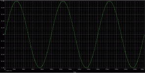
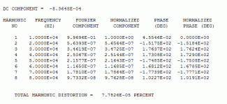
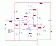
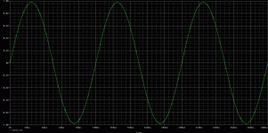
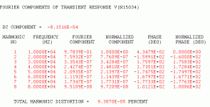
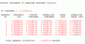
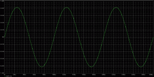
Attached is the starting sim with 50 ohm input impedance and 10k output impedance. Excitation is 1V at 10kHz. A BSS159 is used as a current source load for the follower, and should have higher output impedance than the PN4393 jfet I originally used.
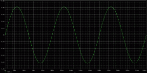
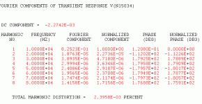
As can be seen, the simulated distortion is quite low. Next up, I'll jack up the source impedance to 1k and I0k, then reduce the load impedance.
Attachments
Last edited:
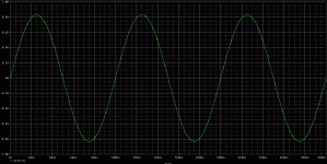
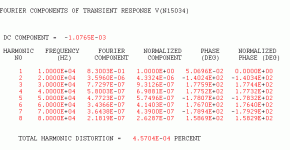
Here's the same circuit with the source impedance jacked up to 1k., with the output loading still at 10k The output is a little lower (voltage divider), and the distortion is a little higher but still quite respectable.
Attachments
Here are the results with 10k input impedance, with the output load still at 10k. The output is lower yet (no surprise), and the distortion, though higher, is still very reasonable.
Later on, I'll start chipping away at the output load.
Later on, I'll start chipping away at the output load.
Attachments
Finally, here's an extreme case with the output load resistance reduced to 2k. This would require in practice increasing the value of the output coupling cap to maintain a decent low frequency response. Distortion is still not bad for a simple source follower circuit.
Attachments
Who know an URL for download this technical articles :
1) Sherwin, J.S., "How, Why and Where to Use FETs,"
Electronic Design,. May 17, 1966, p. 94.
2) Sherwin, J.S., "Knowing the Cause Helps to Cure
Distortion in FET Amplifiers," Electronics, Dec.
12,1966, pp. 99·105.
found in this SILICONIX FETdata book under
https://www.google.de/url?sa=t&rct=...Databook.pdf&usg=AOvVaw3d9hb1R-bK3U4hF_dGcY1J
on page 7-19 (previous sites are also very interesting)
this URLs are also of interest
Try to understand Jfet Distortion and want to design my own.
https://www.kennethkuhn.com/students/ee351/jfet_distortion.pdf
I want to have this these articles because I want to replace 2SK147/2SK170/2SK364 and some other jFETs with high gm/high Cin by good available low gm/low Cin (like BF256B) together with a BjT small signal like BC550C in a darlington or Sziklai darlington configuration for increasing Gm again - have a look also to this topics:
More FET noise measurements (for EUVL) (post #93)
and
https://www.diyaudio.com/forums/pass-labs/375295-audio-uhf-rf-jfet-replacement-5pf-2sk389-2sj109-2sk170-2sj74.html"]Better Audio by UHF/RF jFET Replacement (<5pF) for 2SK389/2SJ109+2SK170/2SJ74
I think, low Cin is a benefit in order to get better sonic performance.
Last edited:
Sadly more old articles have been lost than found. But I think you will like this list:
http://www.one-electron.com/Archives/Semi/Siliconix/Siliconix 1966 Bibliography.pdf
Electronic Design is still alive, barely. They have not been good about storing old articles.
Home | Electronic Design
http://www.one-electron.com/Archives/Semi/Siliconix/Siliconix 1966 Bibliography.pdf
Electronic Design is still alive, barely. They have not been good about storing old articles.
Home | Electronic Design
thank you very much for posting the article overview from Siliconix.
Best possibility would be to go to the University and State Library in Wiesbaden - go to
Hochschul- und Landesbibliothek - Hochschule RheinMain
- they try to obtain the desired material worldwide for making copies.
Best possibility would be to go to the University and State Library in Wiesbaden - go to
Hochschul- und Landesbibliothek - Hochschule RheinMain
- they try to obtain the desired material worldwide for making copies.
- Home
- Source & Line
- Analog Line Level
- Simple Low Distortion JFET Buffer
