Any expert can help me on this problem.STK3102-IV used in Marantz amplifier
PM80SE in pre-amp section it drives 4 output devices. I replaced STK with
STK3102 IV unfortunately not successful no quescent current running. If there
is any modification possible to mount STK with similar rating on the heatsink
with inter change pin connection is highly appreciated.
Crecencio
PM80SE in pre-amp section it drives 4 output devices. I replaced STK with
STK3102 IV unfortunately not successful no quescent current running. If there
is any modification possible to mount STK with similar rating on the heatsink
with inter change pin connection is highly appreciated.
Crecencio
Hi Crecencio,
Looking at the III version, I see pins 5, 11 are constant current sinks and pins 6,10 are the driven outputs. Your driver transistors would be connected between pins 5 and 6 for example. If you have voltage to this chip and no bias, then something (like a resistor) is open, or your bias control circuit is shorted.
Didn't find a sheet on the type IV.
-Chris
Hi Guys,
I checked with version III didn’t make any difference. I think problem somewhere in bias. But look strange in both channels. So how much voltage should i get on pin 5, 6 /10, 11. I measure around + - 1.3 to 1.5.and the STK
Chip gets warm after 3 to 5 min. To drive the bias control circuit 1.5v is sufficient?
Crecencio
Hi Crecencio,
The bias is generated within the STK chip. 1.5V may not be enough, but that voltage is dependant on your output circuit. The actual voltage drop does not matter (within reason) to the chip. It supplies a current, your output circuit drops whatever voltage in response to that current.
Look at your bias circuits. Is the control turned down too far?
Those chips are designed to run warm.
-Chris
Here is something interesting :
We all expect one to replace the 3102 , check soldering , check the known relays issue ,replace a few capacitors , set the bias and done...
I also expect "techs " that simply replace the 3102 and give away .
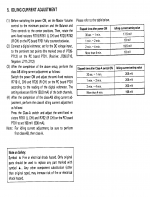
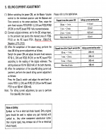
Point is that in the first case and when one wants to set the bias will look at the service manual and bias the amplifier accordingly .The problem is that the service manual is written WRONG !!
It states that at bias points bias should be 18mv over a resistor 0.18R and that equals to 50ma ......Obviously this wrong since this equals to 100ma
farther more in the high bias condition 198mv over a resistor of 0.18 that equals to 500 ma Obviously this is also wrong and equals to 1A
Pm 80 features both neg and pos test points and what the missed to print is that the sum of the two redings ( pos +neg ) should be 18mv and 198 mv respectively .
Cannot tell if more than double the bias will stress the IC but obviously in total the heat will stress the amp and produce fatigue of parts and soldering .
Now days fake IC exist from PMC /SAN which the quality i am not aware off so i replaced one , added a far better heat sink and bias the amplifier properly to see how far i will go ....
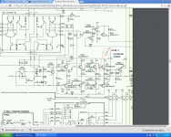
Enjoy a print of the schematic
Kindest regards
Sakis
Attachments
In the text Θυμιος it is not clear that you need to measure between emitters In the pcb also test points do not show that
The test points in pairs normally means that you place your DVM on the test point That will produce wrong result
Farther more for classic Japanese service manuals where test points exist usually work as i described That on its own might drive the tech to an over bias situation ...
Regards
Sakis
The test points in pairs normally means that you place your DVM on the test point That will produce wrong result
Farther more for classic Japanese service manuals where test points exist usually work as i described That on its own might drive the tech to an over bias situation ...
Regards
Sakis
- Status
- This old topic is closed. If you want to reopen this topic, contact a moderator using the "Report Post" button.
- Home
- Amplifiers
- Solid State
- Any modification for replacing STK3102-IV


