Dear Sirs,
I would like to ask kindly to anyone who knows the following data about the original KRELL ksa50 (first series) power supply:
1) number of transformers;
2) VA rating of the transformer/s;
3) number of filter capacitor and their value (uF/V)
4) brand of the transformer and capacitors.
As you can well see I am quite interested in the PS of this little wonderful beast.
Moreover from what I have gathered the first series was the better performing of all.
Comments on this last statement would be very welcome and much appreciated.
Thank you so much.
Kind regards,
beppe61
AndrewT said:Hi Beppe,
I think there were two 400VA transformers inside the stereo KSA50 amp wired as true monoblock.
Have a look at the KSA Wiki for more info.
Dear Mr. Andrew,
thank you so much for the extremely interesting link.
I have found all the info I needed.
Thank you sincerely.
Kind regards,
beppe61
AndrewT said:Hi Beppe,
I think there were two 400VA transformers inside the stereo KSA50 amp wired as true monoblock.
Have a look at the KSA Wiki for more info.
Dear Mr. Andrew,
please excuse me if I take the liberty of asking your opinion.
I have listened to a KRELL KSA50 recently and its powerful bass impressed me much.
I see that it had 2 400VA toroidals and four 40.000uF high-grade caps.
Do you think that its prodigious bass can be related more to the work of the transformer or of the capacitors?
I ask you this because I am always thinking of upgarde an amp of mine and I do not know if it is better to start with the transformer or with the capacitors.
Thank you very much indeed.
Kind regards,
beppe61
Hi Beppe,
I have not started building my KSA Klone yet.
I have a few thoughts, in decreasing order of merit, on why it produces adequate bass:-
1. good current capability.
2. only two RC time constants controlling bass roll off, NFB and PSU.
3. a carefully balanced set of design compromises to maximise use of mechanical and electrical resources, ensuring no weak points.
4. multiple output devices and low output impedance.
5. ClassA
6. 4 & 5 combine to ensure current delivery from 1.
BTW 40mF per rail is about 6mF per Apk of output current into 4ohms. This is about twice what I recommend for a classAB amp.
Agree with Al and Andrew, just to elaborate on point 4.
By virtue of being class-A, the voltage rails are very stiff (or pseudo regulated by virtue of hi/ constant loading).
In lay terms, This means as opposed to a class AB amplifier which has unloaded rails of 45vdc which drops to 37vdc underload, this reduction of vRails as the amplifier is trying to squeeze out a kick drum can make it appear, "soggy".
On the other hand a KSA-50 with unloaded rails of 40vdc (no bias) and fully loaded (full class-A bias) rails fo 37vdc will not droop rails by more than 1-1.5vdc hence the bass will be more consistent and substantial relatively.
Building Better Amplifiers
Scanning through the volume of promotional literature from many 'high end' manufacturers, one could be easily forgiven for concluding that sonic perfection in a power amplifier is only approachable at huge expense in the form of massively overbuilt 50kg behemoths with enormous power supplies, Class A, 20 KHz + open loop bandwidth, and minimal or no global negative feedback (NFB) - and that anything less would severely compromise either sonic performance or available power or both! However, it has subsequently been shown (Ref 1), that the premise on which these designs were conceived is flawed and that far more elegant solutions are possible with clearly audible, and measured, performance benefits (Refs 1,2,3) as well size, weight, cost and, far from the least important, environmental advantages.
Evolution of the Modern-Day Dinosaur
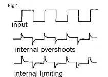
Amplifier design changed direction in the mid 1970's after a new form of distortion was 'discovered' (Ref 4) supposedly resulting from the application of large amounts of global loop NFB. Dubbed transient intermodulation distortion (TIM) this was subsequently displayed as being not stimulated by conventional measurement techniques and thus previously unassessed in the design process. Many designers and manufacturers responded to this by producing low TIM designs with little or no loop NFB and 20KHz+ open-loop bandwidths to eliminate the internal overshoots of conventional designs, unaware that these overshoots are a normal function of NFB and only result in TIM when an internal stage of the amplifier begins to severely distort or limit a signal approaching it's slewing rate limit. (See Fig 1). Loop NFB was singled out as the culprit to be alienated - akin to banning motor vehicles to eliminate road accidents! As a direct consequence of the preoccupation with this one trendy distortion, and the assumed inacceptibility of loop NFB as a design tool, these designs suffered in many performance aspects, primarily poor power supply rejection and high levels of steady state wideband distortions (THD ansd IMD). Further development necessarily centred around reducing power supply impedance and linearising the output stage, with massive high regulation transformers and capacitor banks, and Class A multiple bipolar output stages at enormous size, weight, cost and environmental penalty! However, these designs still suffer from poor IMD performance in the aurally sensitive mid-range, while crosstalk and a high sensitivity of the bass performance to power supply capacitance result in a narrowing of the sound stage and an unnatural, often punchy bass particularly in a.c. coupled designs. Some designers even went to fully regulated individual channel power supplies to reduce crosstalk and retrieve detail and soundstage rather than redesign the amplifier for better power supply rejection. MOSFETs which have substantial fundamental advantages over bipolar transistors, could not be used as their one big shortcoming, transconductance variation, could not be adequately controlled without loop NFB.
Ref 1 Cordell R "Another View of TIM" Audio F/M 1980
Ref 2 Leach W. "An Amplifier Input Stage Design Criterion for the Suppression of Dynamic Distortions" JAES Apr 1981.
Ref 3 Holman T. "New Factors in Power Amp Design" JAES July 1981.
Ref 4 Otala M. "Transient Distortion in Transistorised........ " IEEE Transactions on Audio Sept 1970.
End Part 1
Scanning through the volume of promotional literature from many 'high end' manufacturers, one could be easily forgiven for concluding that sonic perfection in a power amplifier is only approachable at huge expense in the form of massively overbuilt 50kg behemoths with enormous power supplies, Class A, 20 KHz + open loop bandwidth, and minimal or no global negative feedback (NFB) - and that anything less would severely compromise either sonic performance or available power or both! However, it has subsequently been shown (Ref 1), that the premise on which these designs were conceived is flawed and that far more elegant solutions are possible with clearly audible, and measured, performance benefits (Refs 1,2,3) as well size, weight, cost and, far from the least important, environmental advantages.
Evolution of the Modern-Day Dinosaur
Amplifier design changed direction in the mid 1970's after a new form of distortion was 'discovered' (Ref 4) supposedly resulting from the application of large amounts of global loop NFB. Dubbed transient intermodulation distortion (TIM) this was subsequently displayed as being not stimulated by conventional measurement techniques and thus previously unassessed in the design process. Many designers and manufacturers responded to this by producing low TIM designs with little or no loop NFB and 20KHz+ open-loop bandwidths to eliminate the internal overshoots of conventional designs, unaware that these overshoots are a normal function of NFB and only result in TIM when an internal stage of the amplifier begins to severely distort or limit a signal approaching it's slewing rate limit. (See Fig 1). Loop NFB was singled out as the culprit to be alienated - akin to banning motor vehicles to eliminate road accidents! As a direct consequence of the preoccupation with this one trendy distortion, and the assumed inacceptibility of loop NFB as a design tool, these designs suffered in many performance aspects, primarily poor power supply rejection and high levels of steady state wideband distortions (THD ansd IMD). Further development necessarily centred around reducing power supply impedance and linearising the output stage, with massive high regulation transformers and capacitor banks, and Class A multiple bipolar output stages at enormous size, weight, cost and environmental penalty! However, these designs still suffer from poor IMD performance in the aurally sensitive mid-range, while crosstalk and a high sensitivity of the bass performance to power supply capacitance result in a narrowing of the sound stage and an unnatural, often punchy bass particularly in a.c. coupled designs. Some designers even went to fully regulated individual channel power supplies to reduce crosstalk and retrieve detail and soundstage rather than redesign the amplifier for better power supply rejection. MOSFETs which have substantial fundamental advantages over bipolar transistors, could not be used as their one big shortcoming, transconductance variation, could not be adequately controlled without loop NFB.
Ref 1 Cordell R "Another View of TIM" Audio F/M 1980
Ref 2 Leach W. "An Amplifier Input Stage Design Criterion for the Suppression of Dynamic Distortions" JAES Apr 1981.
Ref 3 Holman T. "New Factors in Power Amp Design" JAES July 1981.
Ref 4 Otala M. "Transient Distortion in Transistorised........ " IEEE Transactions on Audio Sept 1970.
End Part 1
Attachments
Wow, interesting.............
Hey, back to the original question, I think bigger caps would be the first thing to try and improve, perhaps with snubbers. Reason for this is that I'm thinking that your ripple would be less and not very much affected by the XFO. Because you are drawing a lot of steady state power, I don't think a xformer change would be as effective, plus larger xfos are much more $$$ than caps.
My krell clone is dual mono with a 700VA transformer and a pair of 64,000 uF caps per channel, bass is simply incredible. Even at "low" bias of about 20WPC bass is very very impressive. I don't have the noticable change in bass performance between low and high bias that others have reported. Then again, I'm using way overspec'd powersupply, and 4 pairs of output devices per channel rather than the original 2. Kind of a krell mutant actually.
AndrewT said:Hi Beppe,
I have not started building my KSA Klone yet.
I have a few thoughts, in decreasing order of merit, on why it produces adequate bass:-
1. good current capability.
2. only two RC time constants controlling bass roll off, NFB and PSU.
3. a carefully balanced set of design compromises to maximise use of mechanical and electrical resources, ensuring no weak points.
4. multiple output devices and low output impedance.
5. ClassA
6. 4 & 5 combine to ensure current delivery from 1.
BTW 40mF per rail is about 6mF per Apk of output current into 4ohms. This is about twice what I recommend for a classAB amp.
Dear Mr. Andrew,
thank you so much for your extremely kind and valuable reply.
Kind regards,
beppe61
Dear Sir,
thank you so much for your very kind and interesting reply.
Let me put some questions between the lines.
Congratulations again for your extremely impressive amp.
Just out of curiosity, which are you speakers ?
I have a pair of Dynaudio that have always sound "dull" in my listening room.
I have big hopes in those Sikorel (hoping that are not fake).
Thank you sincerely and kind regards,
beppe61
thank you so much for your very kind and interesting reply.
Let me put some questions between the lines.
lgreen said:Wow, interesting.............
Hey, back to the original question, I think bigger caps would be the first thing to try and improve, perhaps with snubbers.
That is indeed what I will try first.
I am replacing two 30 years old 7200uF/50V Sprague with two Siemens Sikorel 15000uF/100 V ( I hope to find the space inside).
I read really great words about Sikorel caps. I'll see.
Did you ever carry out any caps upgrade (leaving all others things equal) ?
> Reason for this is that I'm thinking that your ripple would be less and not very much affected by the XFO.
excuse me Sir, what is a XFO?
> Because you are drawing a lot of steady state power, I don't think a xformer change would be as effective, plus larger xfos are much more $$$ than caps.
If caps are high grade and big they are also very expensive.
I found a deal and bought 4 of these Sikorel.
> My krell clone is dual mono with a 700VA transformer and a pair of 64,000 uF caps per channel, bass is simply incredible.
WOWW. This is a power supply ! Congratultions.
Tell me something more about those huge caps.
Did you by-pass them with anything smaller ?
Have you tried your amp with just one transformer or smaller caps?
I am very interested in my test with Sikorel because I will leave every other thing unchanged, just to assess the influence of the new caps for future mods.
And then a very nice high regulation TALEMA toroidal of at least 500 VA.
> Even at "low" bias of about 20WPC bass is very very impressive.
Well, it is not that low actually. 20W class A is a good amount. I think.
> I don't have the noticable change in bass performance between low and high bias that others have reported.
This is very very interesting. So it seems that the high current comes above all from that huge power supply.
How could it be otherwise ?
> Then again, I'm using way overspec'd powersupply, and 4 pairs of output devices per channel rather than the original 2. Kind of a krell mutant actually.
Congratulations again for your extremely impressive amp.
Just out of curiosity, which are you speakers ?
I have a pair of Dynaudio that have always sound "dull" in my listening room.
I have big hopes in those Sikorel (hoping that are not fake).
Thank you sincerely and kind regards,
beppe61
I hope no one minds me butting in, but whilst power supplies are being discussed, I would like to ask a quick question. What is the general opinion regarding resevoir cap sizes? Is it better to use a couple of large (47-56,000uf) cans or a bank of 8 to 12 smaller (10-15,000uf) snap ins?
Also, does anyone produce a suitable (heavy duty) pcb for mounting snap in caps?
Thanks.
Also, does anyone produce a suitable (heavy duty) pcb for mounting snap in caps?
Thanks.
Other point of view:
For a class AB or low bias output stage: use many small capacitors.
On class A amplifiers: big cans !
On the first amplifiers i constructed i used many small ones in parallel because of the divided esr values.
This has been common practice by a number of European manufacturers, the best known: ASR (Schäfer& Rompf) in Germany.
=> http://www.asraudio.de/produkte/emitter1-blue.html
=> http://www.asraudio.de/produkte/pics/emitter2_sk_b.jpg
I believe one of the first to do this commercially with a power amplifier was ALBS, in Germany too, with their Symos diy kit.
Sound quality of the Symos300 wasn't that great, but you got a lot of bang for the buck.
On class A amplifiers, with a smaller decoupling capacitor on the pcb, close to the sources/collectors, it doesn't seem to add that much extra.
I look at it as the difference between a car standing still and one doing 60.
The first one still has to accelerate before being agile, the other has immediate response due to its speed.
Often i found class A amplifiers sounding much faster than AB's despite having comparable specs. The bias should be the key factor.
Noticed the same effect on class AB amplifiers with a number of small capacitors instead of big boys, without a constant bias current the powersupply needs to be able to accelerate on fast impulses.
A big can is like a Hummer, a small cap like a Lotus Elise.
Put a number of Elise's next to eachother and they'll pull the same trailer as the Hummer.
Interesting Jacco,
Let me ask you this... what is the advantage of a big can (low ESR) when you cannot really use the capacitance (unless over time) when needed in the short term, i.e. Music transients. Would the only advantage of a big can be, lets se how long the amp can keep playing after the power is switched off")
If the total capacitance of many smaller is same as one big cap, wouldnt it be better?
In this case, 2 lotuses pulling a trailer with same power as the Hummer, but with greater acceleration?
Let me ask you this... what is the advantage of a big can (low ESR) when you cannot really use the capacitance (unless over time) when needed in the short term, i.e. Music transients. Would the only advantage of a big can be, lets se how long the amp can keep playing after the power is switched off
If the total capacitance of many smaller is same as one big cap, wouldnt it be better?
In this case, 2 lotuses pulling a trailer with same power as the Hummer, but with greater acceleration?
K-amps said:If the total capacitance of many smaller is same as one big cap, wouldnt it be better?
Sure K, but many small cost more money and more space than a biggy.
Main reason for using such big cans in a class A design is to drop voltage ripple, not for fast transients.
In case of say a Krell it helps to deliver fat bass tones, but there the ESR values are not that important.
Capacitance does, NBCI.
Nowadays it can be attractive because of batches of cheap nos small caps offered.
Small caps are more often offered in the web shops than big mamas.
I used to be a true fanatic to parallel small caps, but then there was Mallory.

Dear Mr. Vermeulen,
thank you very much for your very valuable advice.
I would like to be sure to have understood all your points.
Let me please put kindly some further questions to you.
>
Please tell me some more about this point.
Did you fall in love with Mallory caps?
Thank you very much again.
Kind regards,
beppe61
ITALY
thank you very much for your very valuable advice.
I would like to be sure to have understood all your points.
Let me please put kindly some further questions to you.
>
jacco vermeulen said:
Sure K, but many small cost more money and more space than a biggy. Main reason for using such big cans in a class A design is to drop voltage ripple, not for fast transients.
I have to say that for me is not clear enough that old distinction between fast and slow amps.
Do fast amp have any particular measurable characteristic?
Like for instance the ability to reproduce accurately a 10kHz square wave?
> In case of say a Krell it helps to deliver fat bass tones, but there the ESR values are not that important.
Capacitance does, NBCI.
That is a point very important for me that I have problems expecially with bass.
If you had to upgrade a power supply in order to get better bass from an amp do you start increasing capacitance or changing the trasformer with one with better regulation?
My next experiment will be to replace two 30 years old 7200uF Sprague with two new 15000uF Siemens Sikorel.
I have great hopes about this mod.
> Nowadays it can be attractive because of batches of cheap nos small caps offered. Small caps are more often offered in the web shops than big mamas.
I need more bass above all other things. Following your advice I have decided to double the actual capacitance in the power supply.
> I used to be a true fanatic to parallel small caps, but then there was Mallory.
Please tell me some more about this point.
Did you fall in love with Mallory caps?
Thank you very much again.
Kind regards,
beppe61
ITALY
Just to provide some personal experience... i got an old Forte Audio model 3 (200wpc AB) from ebay and while i liked the mids and highs, the bass was not that great. I open it up and find that both channels share 4 24000uF caps 2 each in series so basically each rail had 12000uF and this was shared by both channels, so each channel got 6000uF per rail....
I first installed a couple of 56000uF's per rail, then bypassed them with low esr smaller caps of 10,000uF then bypassed with 1000uF and 0.1uF.
The resultant sound was radically different, the bass is sooo tight and punches hard.
Hard to beleieve its the same amp.
Bottom line, instead of 1 big or many small cap, I went with a hybrid approach and it worked very nicely for me.
- Status
- This old topic is closed. If you want to reopen this topic, contact a moderator using the "Report Post" button.
- Home
- Amplifiers
- Solid State
- KRELL KSA50 power supply - kind request of info.