Orjan,
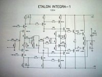
You are correct. The Etalon uses the same type of Hawksford error correction. The way of schematic drawing is a bit different, though, making it less easy to see. Furthermore the Etalon doesn't use emitter followers with series resistors as drivers. The correction normally works by acting on the voltage drop across these series resistors. In case of the Etalon the output is driven from the VAS collectors and the output impedance of the VAS collectors (typically 6k8 from the collectors resistors) serve the same purpose as the former series resistors. There is in principle no difference between a voltage source with series resistance and a current source with parallel resistance.
And yes, the Hawksford paper contains an error in the collector connection of PNP correction transistor. Should be similar to its NPN counterpart.
Marc Vi.'s Ultimate Suplifier doesn't use Hawksford's error correction but uses a different circuit idea described by Hawksford, but probably also used by others. That is R19 and R20 in the Vbe multiplier for the output biasing. Normally these resistors are not there, but Hawksford has shown that better bias stability can be obtained with these resistors included. They compensate for differences in driver base current and thus bias generator current. More info about this in Hawksford paper J8, Optimization of the amplified diode.
http://www.essex.ac.uk/ese/research...cs/J8 Optimization of the amplified diode.pdf
Steven
Steven
That's one doubt I have - if the output transistors are not in the EC path, is it still an Hawksford circuit or just an equivalent?
Is correction as good as can be?
And I agree with the resistors in series with the emitters not been necessary - the circuit I've posted in this thread uses current sources with resistors in parallel.
Re: Steven
Jorge,
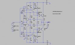
I don't know what you mean. The Etalon circuit *does* have the output transistors in the error correction loop.
The two 560 Ohm resistors serve the same function as your R4/5 (2k8). They are connected to the amplifier output. The ouput signal is compared to the emitter signal of the BC639 and BC640 drivers, via 240 Ohm resistors, like your R6/7.
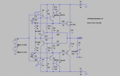
But your circuit is not exactly like Hawksford's proposal. Your R14 and R15 are connected to the bases of Q7 and Q8, while Hawksford's circuit would need them to be connected to the emitters of Q7 and Q8, i.e. at the same nodes as where R6 and R7 are connected to. It would require more time and effort to see how this affects the error correction. From a distance it looks now like you created a local feedback loop (active feedback) instead of an error correction loop. This may also explain why your circuit is quite insensitive to the drive impedances, while for a real error correction topology this would result in a non-minimum error.
Steven
Jorge said:That's one doubt I have - if the output transistors are not in the EC path, is it still an Hawksford circuit or just an equivalent?
Is correction as good as can be?
And I agree with the resistors in series with the emitters not been necessary - the circuit I've posted in this thread uses current sources with resistors in parallel.
Jorge,
I don't know what you mean. The Etalon circuit *does* have the output transistors in the error correction loop.
The two 560 Ohm resistors serve the same function as your R4/5 (2k8). They are connected to the amplifier output. The ouput signal is compared to the emitter signal of the BC639 and BC640 drivers, via 240 Ohm resistors, like your R6/7.
But your circuit is not exactly like Hawksford's proposal. Your R14 and R15 are connected to the bases of Q7 and Q8, while Hawksford's circuit would need them to be connected to the emitters of Q7 and Q8, i.e. at the same nodes as where R6 and R7 are connected to. It would require more time and effort to see how this affects the error correction. From a distance it looks now like you created a local feedback loop (active feedback) instead of an error correction loop. This may also explain why your circuit is quite insensitive to the drive impedances, while for a real error correction topology this would result in a non-minimum error.
Steven
Steven
Yes, I've made a mistake in my circuit...
R14 & R15 should be connected to the emmiters and not to the base of Q7 &Q8.
Re the Etalon circuit:
In the one I have, there's no connection from the output to the emitters of the EC circuit - the circuit 'sees' only a reflected and not the true output voltage.
That's why I've posted that the Etalon is not a true Hawksford.
I haven't simulated it due to a lack of models.
Re: Steven
AFAIK we have been discussing the circuit as attached. If you have a different one (other model?), I'm interested in that circuit.
Steven
Jorge said:
Re the Etalon circuit:
In the one I have, there's no connection from the output to the emitters of the EC circuit - the circuit 'sees' only a reflected and not the true output voltage.
That's why I've posted that the Etalon is not a true Hawksford.
AFAIK we have been discussing the circuit as attached. If you have a different one (other model?), I'm interested in that circuit.
Steven
Attachments
Steven
The circuit I have is this one:
http://www.diyaudio.com/forums/showthread.php?postid=704602#post704602
Well, upon a closer look, the output is connected to the EC through the two servo labels...
Too long a time in management and away from design!
Sorry about the confusion I've made.
Now, correcting the Hawksford basic circuit I've posted, I cannot bias the output devices in class AB/B anymore with the models I have using reasonable resistor values.
And just a note: my 'wrong' circuit has a well defined balance point of minimum distortion, so it's not just plain local feedback.
Regards,
Jorge
Bias problem
Jorge,
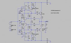
Bias problem: that's understandable, since you use a single output transistor in the correction loop. The Vbe multiplier ends up now multiplying close to one, which does not match the ratio of the repositioned R14 to R4.
Solution options:
1) replace output transistor with darlington
2) incorporate Sziklai driver into correction loop together with output transistor; add emitter followers between G1/2 and Sziklai.
In case of 2) R6 moves to the base of Q7 instead of moving R14 to the emitter of Q7.
Have fun. After all, designing is probably more satisfying than management (although it pays less). I know the problem.
Steven
Jorge,
Bias problem: that's understandable, since you use a single output transistor in the correction loop. The Vbe multiplier ends up now multiplying close to one, which does not match the ratio of the repositioned R14 to R4.
Solution options:
1) replace output transistor with darlington
2) incorporate Sziklai driver into correction loop together with output transistor; add emitter followers between G1/2 and Sziklai.
In case of 2) R6 moves to the base of Q7 instead of moving R14 to the emitter of Q7.
Have fun. After all, designing is probably more satisfying than management (although it pays less). I know the problem.
Steven
Re: Bias
Bias can be OK, but the error correction is still not optimal. You found a clever way of increasing the required bias voltage by including the MURS120 diodes, but...changing base current demands of the output transistors cause changes in diode drop of the MURSs. Base to emitter voltage drop of Q7/8 is fairly constant because the current through Q7/8 is fairly constant. This means that the cathode of D2 follows the input accurately and thus the anode of D2 differs from the input. Still you are using this anode via R8 as if this is the accurate input to be compared with the output of the amplifier via R4/14. Similar story for the bottom half.
Steven
Jorge said:Is Ok now
Bias can be OK, but the error correction is still not optimal. You found a clever way of increasing the required bias voltage by including the MURS120 diodes, but...changing base current demands of the output transistors cause changes in diode drop of the MURSs. Base to emitter voltage drop of Q7/8 is fairly constant because the current through Q7/8 is fairly constant. This means that the cathode of D2 follows the input accurately and thus the anode of D2 differs from the input. Still you are using this anode via R8 as if this is the accurate input to be compared with the output of the amplifier via R4/14. Similar story for the bottom half.
Steven
I think we are at the hair splitting level here.
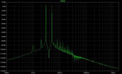
Dynamic impedance of the MURS is less than one ohm with values shown, lower than B-E impedance of another EF (as in a triple EF).
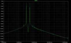
And compares made with a triple EF against the circuit I've posted shows the triple EF to have more distortion (for the same components/bias values, adjusting the 4.6K resistors in 100 ohms steps).
Dynamic impedance of the MURS is less than one ohm with values shown, lower than B-E impedance of another EF (as in a triple EF).
And compares made with a triple EF against the circuit I've posted shows the triple EF to have more distortion (for the same components/bias values, adjusting the 4.6K resistors in 100 ohms steps).
- Status
- This old topic is closed. If you want to reopen this topic, contact a moderator using the "Report Post" button.
- Home
- Amplifiers
- Solid State
- Hawksford output error correction circuit?