Hi Eric
I fully agree !!!!!
I don't bother that much about a non constant impedance driving such an amp, since I don't intend on building anything in the near future anyway where an amp is driven by a non-constant source impedance.
Active crossovers can be regarded as constant impedance sources with quite good accuracy IMO !!!!")
Regards
Charles
what amplifier topologies are there where the first emitter junction is inside the feedback loop? The only one that comes to my mind is a non-differential input stage, where the output signal is fed back to the emitter. This will only work in inverting configuration
I fully agree !!!!!
I don't bother that much about a non constant impedance driving such an amp, since I don't intend on building anything in the near future anyway where an amp is driven by a non-constant source impedance.
Active crossovers can be regarded as constant impedance sources with quite good accuracy IMO !!!!
Regards
Charles
I don't understand the suggestion that using an LTP (long-tailed pair) means the "first" base-emitter junction is not within the negative feedback loop.
A LTP primarily produces a output current that is proportional to the differential voltage between bases divided by the sum of the transconductances. Are not both BE junctions within this equation and therefore within the negative feedback loop?
A LTP primarily produces a output current that is proportional to the differential voltage between bases divided by the sum of the transconductances. Are not both BE junctions within this equation and therefore within the negative feedback loop?
One must consider that every device within the feedback loop is controled by this loop. This mean, if the device introduce any variation, this variation is minored by the overall feedback loop factor.
This in not the case when the input signal and the feedback signal are carried into the amplifier by distinct ways, for instance the base and the emitter of the input transistor. Any variation of the Vbe is not minored by the overall feedback loop factor, and is amplified as is by the whole chain.
The unique solution that I know to this problem is to use parallel feedback, where the feedback signal is carried directly from the output to the amplifier input, mixed with the input signal by a passive network. (This gives an inverting amplifier).
Carefully examining operational amplifier data shows that distorsion figures are always lower in comparison with usual "serial" feedback. Thermal distorsion is very critical in op amps because of the inavoidable thermal coupling between output and input transistors.
Dr Matti Otala has used parallel feedback in his famous Electrocompaniet 25 W, with superior results, and extremely low distortion factor, noticeable performance when one consider the poor quality of the available transistors at the time.
Regards, Pierre Lacombe.
Hi guys
Would appreciate your comments on the thead Measuring sound quality - can it be done ??? in the Pass Labs forum.
Interesting that this thread picked up on the same reference (http://peufeu.free.fr/audio/) I used in making the point that we may not necessarily be measuring the right things.
Best regards
Nic
Pierre wrote:
"This in not the case when the input signal and the feedback signal are carried into the amplifier by distinct ways, for instance the base and the emitter of the input transistor. Any variation of the Vbe is not minored by the overall feedback loop factor, and is amplified as is by the whole chain."
I'm not sure I understand what you are saying. What do you mean by "minored"? If you are saying that deriving a difference signal across a single BE junction will be subject to numerous errors then I definitely agree. However, deriving a difference signal using an LTP and CCS feed to their emitters has got to be one of the most linear subtraction methods ever invented.
My earlier point is that you always have a transconductance error to take into account whether using an LTP or a current summing junction. It is just with an LTP you mitigate the problems of source impedance affecting the closed loop gain. It would be worth writing the gain equations down for both configurations before assuming one is better than the other.
phase_accurate said:Hi Eric
I fully agree !!!!!
I don't bother that much about a non constant impedance driving such an amp, since I don't intend on building anything in the near future anyway where an amp is driven by a non-constant source impedance.
Active crossovers can be regarded as constant impedance sources with quite good accuracy IMO !!!!
Regards
Charles
Err, I meant to say the signal is fed back to the BASE of the single input transistor, of course.
Is this what you are using in your active XOs? What about thermal distortion due to the temperature dependence of the operating point? Wouldn't that be greater than in the same inverting configuration with a LTP?
Cheers,
Eric
P.Lacombe said:One must consider that every device within the feedback loop is controled by this loop. This mean, if the device introduce any variation, this variation is minored by the overall feedback loop factor.
This in not the case when the input signal and the feedback signal are carried into the amplifier by distinct ways, for instance the base and the emitter of the input transistor. Any variation of the Vbe is not minored by the overall feedback loop factor, and is amplified as is by the whole chain.
The unique solution that I know to this problem is to use parallel feedback, where the feedback signal is carried directly from the output to the amplifier input, mixed with the input signal by a passive network. (This gives an inverting amplifier).
Carefully examining operational amplifier data shows that distorsion figures are always lower in comparison with usual "serial" feedback. Thermal distorsion is very critical in op amps because of the inavoidable thermal coupling between output and input transistors.
Dr Matti Otala has used parallel feedback in his famous Electrocompaniet 25 W, with superior results, and extremely low distortion factor, noticeable performance when one consider the poor quality of the available transistors at the time.
Regards, Pierre Lacombe.
Superficially, there seems to be a difference between series and parallel feedback (why is it called that way??) in that you use two different transistor bases or just one transistor base for the feedback signal. But in reality, in both cases, it is the difference voltage between the the bases that drives the amp, and the true summing node is the common emitter of the LTP. Any differences in the BE voltages of the two input transistors will result in a feedback error.
The true reason why parallel feedback will give superior distortion, in spite of increased noise gain, is that the bases and emitters sit at a fixed voltage, whereas in series feedback, the bases and emitters follow the input signal which results in common mode distortion, e.g. from imperfect matching of the parasitic Miller capacitances or source impedances.
Regards,
Eric
Nelson Pass said:"Pass amps are not really in the forefront regarding low distortion,
so thermal distortion may be 3rd or 4th order effects in them,
but in very low distortion/high precision amps thermal dist may have a much more pronounced effect."
The character of Pass amps is a function of simplicity and low feedback.
If you make the circuit more complex and apply lots more feedback,
the thermal distortion is still going to be in the dirt.
Yeah, Nelson, I know.'simplicity & beauty' and yet high quality in sound.
But, please, you tell me something about your creations,
that I am not already familiar with.
There has to be plenty of such things, yet unknown.
capslock said:
Nelson & Steve,
the Audionet amps seem to have extremely low distortion, and they are getting extremely good reviews (whatever that tells us).
Hartmut,
what does LTP stand for?
capslock
LTP = Long Tailed Pair
.. and we do not refer to the legs of one photo model
We mostly refer to a transistor pair acting as a balance
just like some old weighing-machines
You put weight into one side until you get a good balance (same weight)
Appendix A.
In this picture 100 KG is the output of amplifier.
And the input is the small weight of 1 KG
The lever center is LTP pair transistors.
The both arms difference in length, makes the lever be in BALANCE,
evethough input is much smaller than output.
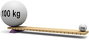
LTP input compares The input signal with a portion, a sample of the Output signal
and then tries to make them as Equal as Possible = Zero Distortion
Also can be called correctional feedback.
Like what you can use to teach your children; what to do & what not to do Lineup
A couple of remarks as this thread reactivates.
As has been pointed out, thermal distortion is not at all new, and was noticed even with vacuum tubes---but as also mentioned, its study was necessitated by oscilloscope vertical amplifiers, and exacerbated when these migrated to solid-state.
In articles about such amps, by Tektronix and probably others, it was mentioned that the time constants involved with small-geometry fast transistors associated with uncompensated thermal shifts could be in the ~few microsecond range.
The reason thermals are so important for analog 'scopes is that when they are striving for ultimate speed, they cannot use (signal-bandwidth) global feedback without compromising that speed.
For a good treatment of thermal distortion and designs that minimize it, see Feucht's book Handbook of Analog Circuit Design(ISBN 0122542401). Feucht learned his lessons well at Tektronix (I believe).
Wihout knowing of the 'scope work, which was hard to find at the time, I did some non-audio designs in which I generated fast pulses and kept the active device dissipations constant. They worked fine, and I wondered about extending the results to audio. This was at UCLA, circa 1974-1983.
I haven't looked at the Perrot claims in detail. They may be specific enough to survive a challenge---I don't know. But of course they are fine to know about and play with for DIY.
The other remark: it has been stated that with high quiescent dissipation, a delta dissipation will be correspondingly less significant. This is not usually correct---the variation in a temperature-dependent parameter, like beta say, is not going to change much by running the part at a higher quiescent dissipation. Intuition misleads here.
Brad
another related thread:
http://www.diyaudio.com/forums/showthread.php?s=&threadid=100810
where I point out that input diff pair thermal distortion is easily eliminated by simple circuit techniques that should be employed on their other merits in any low distoriton amplifier:
http://www.diyaudio.com/forums/showthread.php?s=&threadid=100810
where I point out that input diff pair thermal distortion is easily eliminated by simple circuit techniques that should be employed on their other merits in any low distoriton amplifier:
jcx said:..."the formula" for practically eliminating thermal distortion in the input diff pair is simple:
cascode - bootstrapped to the common mode input V
and high loop gain after the diff pair to reduce diff signal - easily down to uW
Before starting discussion about thermal (memory) distortions, it’s better to understand which parameters of these distortions forces on audio signal and which result. In practice we can speak about two types of forces: amplitude modulation and additional impulse signal. These forces have two general characteristics: timing and amplitude. Not of all combinations on these parameters reduces quality of audio signal. As I know, amplitude modulation with timing about 1 ms is very audible in reducing of signal source recognition. This distortion type is very important because it becomes on signal rising. Impulse signals with timing from 100 us to 10 ms can audible as dirt. Amplitude modulation with timing about 100 ms change emotional coloring. Probably where are more forces with other parameters witch I don’t know.
In different circuit topologies thermal distortions appears with various result.
If we look on classic power amplifier like operational amplifier, most important points of thermal distortions appearance are differential cascade and output cascade. Changing of offset of input cascade by thermal modulation don’t compensated by feedback. Therefore input cascade is more guilty in appearing of dirt. Amplitude modulations of all cascades in this amplifier are compensated by feedback. Thermal distortions of output cascade are compensated by feedback, but it has large value and become guilty anyway. Thermal timing of power transistors depend on crystal size. Therefore transistors with large crystal carry in lower audible distortions. Using of class A or AB in output cascade don’t affect on thermal distortion level because thermal distortions are proportional to power dissipation change (not absolute value of dissipation). But disposition of thermal distortion in these classes is different. Power dissipation of output transistor in class A likes square function. In class AB function is changed from square in low signal to linear on middle and to square (with wide spectra) on large signal. This mean changing of coloring musical signal on changing of signal amplitude.
I discover this thread only today.
What it has not been stated above about Perrot is that, at the end of his famous writings in "L'Audiophile", he proved to be unable to show that a standard amplifier with NFB suffers from thermal distorsion.
Douglas Self said that thermal distorsion would increase harmonic distorsion at low frequencies. This effectively happens in power IC's but not in amplifiers using discrete components.
Thermal distortions of ICs and discrete amplifiers have some different source. In ICs, main thermal source - output transistors. Because of those transistors work in class AB, thermal flow is not linear. Therefore harmonic distortions in power ICs grow in low frequencies. In discrete amplifier main thermal source is the same transistor. Input transistors work in deep class A and thermal functions are much linear. But changing of thermal dissipation makes changes of transistor offset and amplitude modulation of sound formants, that is audible as decrease of naturalness.Douglas Self said that thermal distorsion would increase harmonic distorsion at low frequencies. This effectively happens in power IC's but not in amplifiers using discrete components
These distortions are well simulated by spice with thermal models of transistors. We made some experiments. We used several standard schemes and entered it into LTSpice. As signal source we used three short musical fragments in wav format. Output signal was written in corresponded wav files. Those operations were made with thermal models and without. Results were published in one diy forum without comments. Peoples listened fragments and put comments. All comments were consolidated. As result, most people have selected fragments without thermal distortions as better.
Kostya-M,
Maybe not very surprisingly.As result, most people have selected fragments without thermal distortions as better.
forr said:I discover this thread only today.
What it has not been stated above about Perrot is that, at the end of his famous writings in "L'Audiophile", he proved to be unable to show that a standard amplifier with NFB suffers from thermal distorsion.
Douglas Self said that thermal distorsion would increase harmonic distorsion at low frequencies. This effectively happens in power IC's but not in amplifiers using discrete components.
NFB will help in some topologies but not that much in others. If there is significant dissipation change, especially in an input device, unless it is compensated for in some fashion you will get parameter shifts and associated distortion. This is independent of the discrete versus IC construction. However, without careful layout mindful of thermal changes, the IC component proximity will make matters far worse.
Hi Lomba Ogir
---many parameters are temperature-dependent. What is to be shown?---
Harmonic distorsion which is our first friend to investigate anomalies inside amplifying circuits.
According to Perrot, thermal distorsion will firstly emanate from the input stage. On a small 0.3W transistor, I've measured a thermal time constant of about 5 mS (I did not intend to be precise, it was just an evaluation). This seems to me to be very short. So input stages of discrete amps should be thermally modulated at very low frequencies and show an increase of harmonic distorsion in this region where the bias of the ouput stage is not so important. They do not, I wonder why.
Some speculative numbers :
The input stage of the blameless amp runs at 3 mA in each transistor.
A variation of 1 V at the input produces a power variation of 3 mW.
Considering that the thermal resistance of a junction is 200°C/W for a 0.3 W transistor, 3 mW would produce a temperature variation of 0.6°C.
With a Vbe variation 2.1 mV for 1°C, the Vbe variation should be a bit more than 1 mV, without Re degeneration. That's quite important. Am I right ? Even amps without Re degeneration have not been shown having harmonic distorsions at VLF.
Everything indicates that solid-state amps should be very sensible to thermal modulation. However it is rather impossible to prove that real amps suffer from it. Self says that, if thermal distorsion exists, it is entirely hidden by noise.
I have the projet to test harmonic distorsion at 1 kHz in devices submitted to slow sinus variations (3 Hz) of the power they dissipate. Distorsion components should show jiggles at the same rate.
If the blameless amp has both sides of the input pair changing in power dissipation equally, Vbe's will tend to track and the resulting error should be fairly small. This presumes sufficient loop gain so that the change in differential voltage and current is small.
There will be another effect due to beta change, which is something on the order of +0.5% per degree Kelvin. If the impedances at each base differ this will also produce an error. Also transistor mismatch will make things worse. These will not be mitigated with NFB in general.
Admittedly the problem with well-designed global feedback amps is much less severe than various less-closed-loop topologies. It is not surprising that oscilloscope vertical amplifier designers were the first to develop circuits to cope with thermal distortion. Also, the push to ever-higher frequencies meant smaller geometry devices and high current densities, hence exacerbating things. I recall a Tektronix article about how they had seen effects out to 1MHz!
Hi Bcarso,
The differential stage may help, but the thermal constant is short and in many implementations, the dissipation in each device is a litte different between positive and negative excursions.
I have no exemple of VLF distorsion in mono-transistor input stage.
whre thermal effects should be much more sensible. Worth investigation too.
I do not think the name of the Tektronix circuit has been given. It's called "cascomp". I am very fond of that kind of circuits, many of them were shown and measured by Perrot : Van De Plaasche, Caprio, Cascomp, CFP cascode...
- Home
- Amplifiers
- Solid State
- comments on thermal distortion?