Say a 100 times more - I grabbed one for-spares Teac A-70 from a well-known auction site for 25 quid (+35 in postage and import fees - thanks Brexit!Unfortunately you have to buy vintage amplifiers like Teac A70 to get the 2SK170 Y grade jfets.
I have researched this too but it´s a long and expensive way to take.
The 2SJ74 Y is even harder to get.
Matching them will probably rise the problem 10 times more.
 ); it's chock-full of dust, and doesn't seem to have been tampered with in any way, but the JFETs are 2SK170GR, not Y. My guess would be Teac switched to the GR-grade parts after Toshiba had at some point stopped manufacturing the Y's. Hence, the year of manufacture of a particular A-70 unit could be of importance here...
Today I measured the test amplifier board and I am really impressed.
You could feed it with (1KHz) 960-980mV p-p before you overdrive it and the positive wave starts clipping slightly before the negative wave.
The output is 21,8-22.0V p-p.
You can see the clipping when I feed it with 1,02V p-p.
The last picture is the full power at 100KHz, almost 22,8V p-p before clipping.
In this picture I used 26V to power the amplifier (like the batteries I will use).
At 100KHz the current in the power stage was 900mA.
The current consumption started to rise at 50KHz and driven it at 100KHz for some time the heatsink got quite warm.
In the last picture I removed the 470pF capacitor I had installed in parallell with R12 (220ohm feedback resistor).
Caused some phaseshift and I will not use it in my design.
The amplifier was stable during all tests and behaved as it should.
No ringing and the FFT analyse was ok.
My tone generator is antique and is really bad, I can not draw too much conclusions from the FFT analyse at this point.
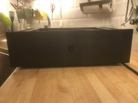
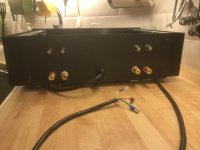
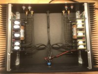
Added 2 pics of my current Hiraga amplifier I built 2017.
It is a dual mono pcb with volume control and 2x45Ah battery inside the chassi. Capacitors is 4 x 47.000uF Rifa PEH169.
It is build with TIP2955/3055 and BC550/560 and 2SK246/2SJ103 (Y).
Will be nice to compare them soon.
Still waiting for some more jfets (2SJ74 GR) to get matched pairs.
You could feed it with (1KHz) 960-980mV p-p before you overdrive it and the positive wave starts clipping slightly before the negative wave.
The output is 21,8-22.0V p-p.
You can see the clipping when I feed it with 1,02V p-p.
The last picture is the full power at 100KHz, almost 22,8V p-p before clipping.
In this picture I used 26V to power the amplifier (like the batteries I will use).
At 100KHz the current in the power stage was 900mA.
The current consumption started to rise at 50KHz and driven it at 100KHz for some time the heatsink got quite warm.
In the last picture I removed the 470pF capacitor I had installed in parallell with R12 (220ohm feedback resistor).
Caused some phaseshift and I will not use it in my design.
The amplifier was stable during all tests and behaved as it should.
No ringing and the FFT analyse was ok.
My tone generator is antique and is really bad, I can not draw too much conclusions from the FFT analyse at this point.
Added 2 pics of my current Hiraga amplifier I built 2017.
It is a dual mono pcb with volume control and 2x45Ah battery inside the chassi. Capacitors is 4 x 47.000uF Rifa PEH169.
It is build with TIP2955/3055 and BC550/560 and 2SK246/2SJ103 (Y).
Will be nice to compare them soon.
Still waiting for some more jfets (2SJ74 GR) to get matched pairs.
Attachments
Gain structure?What`s wrong with the GR grade?
Say a 100 times more - I grabbed one for-spares Teac A-70 from a well-known auction site for 25 quid (+35 in postage and import fees - thanks Brexit!
OK, sorry if I fooled you. The component list says 4x 2SK170 Y-grade.
Teac got problem to find them and had to change the original design for sure.
Thanks for your reply.
@Xlarge What do you expect from the two LC groups inserted into the power rail?
Nothing really, my first thought was to isolate the input section with a 10ohm resistor and a capacitor.
Found the 470uH 9,5ohm inductor and used it instead.
It may give a more stable voltage to the sensitive input stage during large swings in the music.
Tested it and found only 33-35mV drop over them and I thougt, it is better to add them to the board design if you want them, you can short circuit them later on if you do not want them.
Gain structure?
The GR grade has a higher IDSS current.
Gives you more current in the input stage and you will have to redesign some resistor values to get the right voltages and bias current in the output stage.
Wow that is a thing of beauty, would you consider sharing the gerbers?
I have now verified the PCB as you can see in my post.
Still interested in the PCB?
I can send you the Kicad files if you want to redesign something or the Gerber.
Remember it is designed for 5.08mm TX-2575 resistors but you can always use ordinary metal film types and bend one leg (stand up).
Did this on the test PCB I measured.
OH YES PLZ, I have been super busy and didn't see this. I have not yet had time to start my "learn design software" effort but the Gerbers would be great. I am happy giving away the spares too. I'll pm you my email.
Also if anyone is interested I have 2 spare PO89ZB filter boards, free if you pm me.
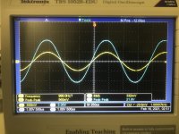
Today I measured the test amplifier board and I am really impressed.
You could feed it with (1KHz) 960-980mV p-p before you overdrive it and the positive wave starts clipping slightly before the negative wave.
The output is 21,8-22.0V p-p.
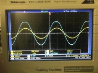
You can see the clipping when I feed it with 1,02V p-p.
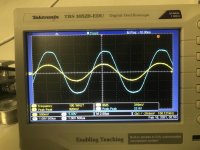
The last picture is the full power at 100KHz, almost 22,8V p-p before clipping.
In this picture I used 26V to power the amplifier (like the batteries I will use).
At 100KHz the current in the power stage was 900mA.
The current consumption started to rise at 50KHz and driven it at 100KHz for some time the heatsink got quite warm.
In the last picture I removed the 470pF capacitor I had installed in parallell with R12 (220ohm feedback resistor).
Caused some phaseshift and I will not use it in my design.
The amplifier was stable during all tests and behaved as it should.
No ringing and the FFT analyse was ok.
My tone generator is antique and is really bad, I can not draw too much conclusions from the FFT analyse at this point.
Added 2 pics of my current Hiraga amplifier I built 2017.
It is a dual mono pcb with volume control and 2x45Ah battery inside the chassi. Capacitors is 4 x 47.000uF Rifa PEH169.
It is build with TIP2955/3055 and BC550/560 and 2SK246/2SJ103 (Y).
Will be nice to compare them soon.
Still waiting for some more jfets (2SJ74 GR) to get matched pairs.
Beautiful work !
Nothing really, my first thought was to isolate the input section with a 10ohm resistor and a capacitor.
Found the 470uH 9,5ohm inductor and used it instead.
It may give a more stable voltage to the sensitive input stage during large swings in the music.
Tested it and found only 33-35mV drop over them and I thougt, it is better to add them to the board design if you want them, you can short circuit them later on if you do not want them.
I dont think it is a good idea to isolate the input stage from the output stage.
As the output stage uses the rail(s) as reference, the input stage should use the same reference point. Think about it.
Thorsten
It isn't fully isolated, and his last mention is to skip the resistance and just short it, as a option, the resistor is also used by dr leach, I like the idea, and have myself thought of breaking the ground plane on my hiraga 30w, and put a 10 ohmish resistor between.
Just for bragging, I bought a 12 kilo ecore dual 20 volt today for my hiraga, 25 amps pr rail, doesn't get much stiffer
Just for bragging, I bought a 12 kilo ecore dual 20 volt today for my hiraga, 25 amps pr rail, doesn't get much stiffer
Last edited:
FYI, I checked with Linear Systems RE the possibility of obtaining J74Y / K170Y equivalents from them - more info here: JFETs from Linear Systems
Do you have a pic of the assembled board?
Sorry for the delay, busy listening the last days.
It sounds fantastic, but my old speakers is a limitation now.
Anyone used Focal Aria 948 speakers with Hiraga amplifier?
Good sensitivity of 92,5dB will probably match this amplifier well.
I will test a pair on Monday.
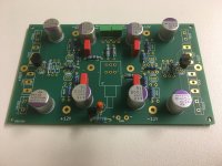
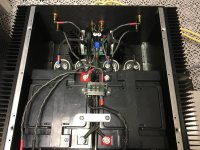
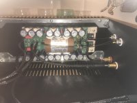
Here is some pictures of the assembled amplifier.
The 4 input transistors/jfets are glued together to get thermal stability.
Almost impossible to see on the picture.
The innermost RCA input is AC coupled and the outer RCA is DC coupled.
Ground is only connected to the AC input otherwise you get a ground loop.
Connect ground together at the RCA inputs.
Speaker output ground is connected from the central ground plane at each channel where input ground from the batteries is connected.
Attachments
Last edited:
It isn't fully isolated, and his last mention is to skip the resistance and just short it, as a option, the resistor is also used by dr leach, I like the idea, and have myself thought of breaking the ground plane on my hiraga 30w, and put a 10 ohmish resistor between.
Hey Dude!
This is not about a PCB. It is about how the curcuit works or doesnt.
We are all here to learn.
I dont know the Leach AMP.
I agree that in 95% of all power amps it is a good idea to isolate the input stage by an RC or LC. But not in the Monster.
Lets look at the upper half of the AMP:
The output stage (consisting of driver and power trans and the 1ohm resistor) can be considered as one gain block with one high impedance output and two inputs. The two inputs are: the top of the resistor and the base of the driver. The output stage will amplify any voltage difference between those two inputs.
Now imagine some dirt on the rail. If you filter the input rail, you will have dirt at one input but not at the other, and this dirt will be amplified by the output stage. On the other hand, if you dont filter the input rail, the same dirt will apear on both input and therefore not have much influence on the output signal.
So, in this case, filtering the power line to the input will be counter productive, if your goal is to increase power supply rejection.
Hope this helps, else someone else might be able to explain it more clearly.
If anyone is interested in this topic, check out John Broskis Aikido principle at tubecad.com, as he has written many pages about different ways to increase power supply rejection.
I can also referr to authority: If it was a good idea, His Holyness Jean Hiraga would have done it, but he didnt.
Best wishes
Thorsten
- Home
- Amplifiers
- Solid State
- Hiraga "Le Monstre"