Interesting, or puzzling. The Sanken's are Darlingtons, with very high Hfe (and surprisingly still way faster than your OnSemi's....) They reduce the drivers current to the µA region, which will not increase performance usually.
More power? How do you measure/determine power?
Just looking at the circuit, I'm anyway not sure how much phase margin it has, and faster devices, operating at currents where they are at their Ft peak, may help. How fast is your scope to look for oscillations?
If you buy more transistors from OnSemi, I suggest you'll try MJL4281A MJL4302A, MJL1302A MJL3281A or the likes.
Last edited:
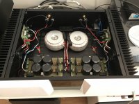
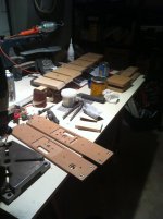
Hi, this is my "Hiraga monster"...
I use 2 x 47000 CRC in each supply rail. Transistor TIP3055 TIP2955, JFET 2SK246 2SJ103, BC for drive output.
Sound is great...
Since it is easy to change the components I would like to try other solutions. Tips?
Bye")
I use 2 x 47000 CRC in each supply rail. Transistor TIP3055 TIP2955, JFET 2SK246 2SJ103, BC for drive output.
Sound is great...
Since it is easy to change the components I would like to try other solutions. Tips?
Bye
Attachments


Hi, this is my "Hiraga monster"...
I use 2 x 47000 CRC in each supply rail. Transistor TIP3055 TIP2955, JFET 2SK246 2SJ103, BC for drive output.
Sound is great...
Since it is easy to change the components I would like to try other solutions. Tips?
Bye
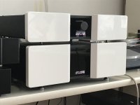
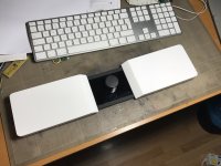
Dino that case is lovely man! Did you build and design that yourself? Lovely build!
Btw, with the Sankens's, you could throw out your drivers, and change PNP with NPN and vice versa. A FirstWatt F5 bipolar, so to say.
How interesting? So are you saying they are not suitable?
Hi, this is my "Hiraga monster"...
I use 2 x 47000 CRC in each supply rail. Transistor TIP3055 TIP2955, JFET 2SK246 2SJ103, BC for drive output.
Sound is great...
Since it is easy to change the components I would like to try other solutions. Tips?
Bye
Beautiful work
View attachment 705818
This is at 0.6A with a 1khz signal at 8ohm
View attachment 705819
0.6A at 4ohm
View attachment 705820
1A at 8ohm
View attachment 705821
1A at 8ohm
on my scope it just shows its more stable at a lower bias. All of this was done at full warm up and just before it clipped.
Hi Vishalk,
Can you measure your power supply rails voltages at 0.6V bias and 1.5A bias and compare?
Good Plan Dan, another thing to note. When I set the bias say to 0.6v my dcoffset goes to say 2v at which point i can't zero it, But if I change the bias it brings it to zero but my bias is like 0.63 on one transistor and 0.61 on the other. As I change either the bias or dcoffset it has an overall effect by changing all the values until its stable.
More so with these sanken Darlingtons.
More so with these sanken Darlingtons.
No, they seem to work anyway. It's just that the original circuit wasn't designed with darlingtons in mind. But if it measures reasonably and, most importantly, doesn't oscillate, it's OK.How interesting? So are you saying they are not suitable?
I suggest also to do an FFT, eg with a soundcard (be careful to not blow it, divide the amp output down...) and Arta, REW or whatever software suited for the task.
With R2 and R3 as trimmers, strictly speaking you wouldn't even need an offset trimpot. Set it to midpoint, and try to trim bias and offset only with R2 and R3 trimmers. Equal bias current of each output transistor essentially means zero offset.[...]As I change either the bias or dcoffset it has an overall effect by changing all the values until its stable. [...]
Interesting, or puzzling. The Sanken's are Darlingtons, with very high Hfe (and surprisingly still way faster than your OnSemi's....)
Superior Japanese technology, unfortunately not suitable for this purpose.
They reduce the drivers current to the µA region, which will not increase performance usually.
Certainly not.
More power? How do you measure/determine power?
That's a very good question.
Hiraga`s designs do not permit themselves to be improved easily. He specified the hFE rank of the output transistors to provide appropriate driving current. Poor parameter matching between NPN and PNP devices results in instability. Only transistors of Japanese design and fabrication are in practice qualified for (this) complementary topology. Also an excessive bias current will cause high distortion.
Please do not use (any) Darlingtons, they may blow up at that bias in that circuit. There are similar Sankens, not Darlingtons. Darlingtons has an extra pair driver built-in, you do not need that in this circuit. Fewer semiconductors in this circuit I think will sound better and will be more reliable.
Dino that case is lovely man! Did you build and design that yourself? Lovely build!
Thank you for appreciation!
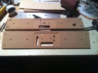
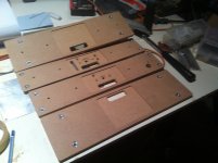
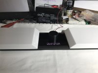
Yes... handmade homemade...
MDF, plexiglass for the front panel (in place of the aluminium original panel) on standard U3 U4 cases.
Bye
Attachments
Voltages, instability, Darlingtons.
I have to agree i've been playing around with the darlingtons mainly at 0.6v, 1.0v and 1.5V.
it takes time and patience to get the bias, dcoffset stable and working together, i have to fiddle and move each potentiometer at different positions,i could never have done this without installing those potentiometers.
Dan for you the voltages
0.6V (more stable, easy to setup and sounds better)
V+ 16.31 V- 16.33
1.0V
V+ 15.89 V- 15.98
1.5V
V+ 15.38 V- 15.44
Well these do work it's a ball ache to setup but at 0.6V they do sound good!
Would i use them? Probably not!
No, they seem to work anyway. It's just that the original circuit wasn't designed with darlingtons in mind. But if it measures reasonably and, most importantly, doesn't oscillate, it's OK.
I suggest also to do an FFT, eg with a soundcard (be careful to not blow it, divide the amp output down...) and Arta, REW or whatever software suited for the task.
I have REW and a mini dsp mic, i usually use this for measuring speakers. What did you have in mind?
Can i do a frequency sweep of the amplifier and measure it?
Thanks for the recommendations on transistors.
Please do not use (any) Darlingtons, they may blow up at that bias in that circuit. There are similar Sankens, not Darlingtons. Darlingtons has an extra pair driver built-in, you do not need that in this circuit. Fewer semiconductors in this circuit I think will sound better and will be more reliable.
Agreed, They handled the tasks ok garborbela, i had them at 1.5A for about three hours and they were fine. As i said they are much happier at 0.6-1A.
Will compare with the MJL soon, just waiting on the driver transistor to be delivered.
Superior Japanese technology, unfortunately not suitable for this purpose.
Hiraga`s designs do not permit themselves to be improved easily. He specified the hFE rank of the output transistors to provide appropriate driving current. Poor parameter matching between NPN and PNP devices results in instability. Only transistors of Japanese design and fabrication are in practice qualified for (this) complementary topology. Also an excessive bias current will cause high distortion.
Can you or anyone else recommend their choice of transistors they use? Or what specifications i should be looking for i.e hfe etc thanks
Those OnSemi I mentioned are OK, and are sustained Beta types.Can you or anyone else recommend their choice of transistors they use? Or what specifications i should be looking for i.e hfe etc thanks
Sanken sure has good Transistors, like eg 2SC3519 and its PNP sibling, it may be difficult to get specific hfe ranks though.
Look at high hfe, not dropping at higher collector currents. hfe (Beta) = 50 @ 3A is already too low for your drivers, with max. 50mA collector current. Luckily you run them hot which increases beta
fT higher than 15 MHz, low Cob. The Sanken are good in this regard.
You don't need the Mic. Drive the Amp directly with your Soundcard output, and route the output of the amp back into the soundcard input.I have REW and a mini dsp mic, i usually use this for measuring speakers. What did you have in mind?
Can i do a frequency sweep of the amplifier and measure it?
Thanks for the recommendations on transistors.
What soundcard do you have?
WARNING:
You must divide the Amp Output down through a resistive divider!!
Otherwise you'll fry your soundcard.....
Chose a ratio that will bring the levels back to the soundcard output level (if your Amp has a gain of 20x, divide it at least by 20), before feeding the soundcard. A good thing would be to additionally protect your SC input by back to back zener diodes (3.3V types would be OK).
Take care that your Soundcard (PC) and Amp share the same ground.
REW has Help Files, on a first glance the following apply:
Signal Generator
RTA Window
Distortion Graph
Start with a sine at 1000 Hz (you may load the amp with your preferred 4 or 8 Ohms load, of course), and look at the spectrum (RTA Window).
Start with low levels, increase them, play around. Look what happens when the amp clips. Look what happens when you measure with higher frequency, eg. 4 kHz. Look what happens when you feed dual sine.
The distortion graph needs sweeped sine, or so.
You can learn a lot looking at an FFT graph.
- Home
- Amplifiers
- Solid State
- Hiraga "Le Monstre"