Hi everybody !
I'm new here and I need a hand.
I have an old rega brio integrated amp with one dead channel on the power amp. I don't know what happened to it, I just got it like that.
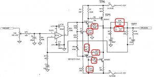
So I opened it. Besides the fuse, there are a few resistors that are badly burnt. The schematics show which ones.
My question is: how should I proceed to fix it ? I mean which method should I follow.
-Should I change everything in the faulty channel, including all transistors and just set idle current at the end ?
-Are there any other components that are most likely dead too ?
-Should I only change the burnt resistors ?
I have an oscilloscope, a digital multimeter. And I'll use my PC as a signal generator to feed the preamp.
And I'm willing to spend some time on it because I find it interesting. Otherwise I'd have it serviced but it's a lazy option.
I would really appreciate the help of one of you guys. I am far from having your skills, but I studied electronics at school and can use all the instruments I listed. If I need something more, please tell me.
Thanks in advance.
I'm new here and I need a hand.
I have an old rega brio integrated amp with one dead channel on the power amp. I don't know what happened to it, I just got it like that.
So I opened it. Besides the fuse, there are a few resistors that are badly burnt. The schematics show which ones.
My question is: how should I proceed to fix it ? I mean which method should I follow.
-Should I change everything in the faulty channel, including all transistors and just set idle current at the end ?
-Are there any other components that are most likely dead too ?
-Should I only change the burnt resistors ?
I have an oscilloscope, a digital multimeter. And I'll use my PC as a signal generator to feed the preamp.
And I'm willing to spend some time on it because I find it interesting. Otherwise I'd have it serviced but it's a lazy option.
I would really appreciate the help of one of you guys. I am far from having your skills, but I studied electronics at school and can use all the instruments I listed. If I need something more, please tell me.
Thanks in advance.
Attachments
Found something
Hi there !
I realise it was a complex question, so I went searching a lot more. Well, I found this:
http://sound.westhost.com/troubleshooting.htm
It looks really good, just what I wanted. You might know it already. I post it in case some of you don't.
But there are still a few questions for you guys:
-What's your opinion about this amplifier, looking at the diagram ?
-What are your ideas to improve it ?
Regards
What a coincidence! I have the same amp with one channel dead. When I opened it, one fuse was blown. And two resistors.
But I don't see the resistor number listed on your schematic. Is that the complete schematic?
Maybe you have another part of the schematic.
Your help is highly appreciated.
Frank
But I don't see the resistor number listed on your schematic. Is that the complete schematic?
Maybe you have another part of the schematic.
Your help is highly appreciated.
Frank
It is likely that T1, T2, T5 and T6 will be blown. You should replace these. Also check the op-amp is working. You may as well replace all the transistors as there's so few of them. You might be better dropping a better op amp such as NE5532 in there instead of the TL072 too, but if all you want is to get it working, replace with a TL072.
It's not exactly a very well designed amplifier. The driver transistors are only rated for 100mA, and well, the 2955/3055 is older than time. Theres also no resistance to isolate the 2955/3055's from the speaker line. Looks like a recipe for disaster when it goes wrong.
Don't bother getting it serviced if you can do it yourself. Luckily the low parts count means it's relatively cheap to replace all the parts in the channel. You can get all of the transistors from OnSemi as samples
Don't bother getting it serviced if you can do it yourself. Luckily the low parts count means it's relatively cheap to replace all the parts in the channel. You can get all of the transistors from OnSemi as samples
Layout
Hi,
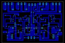
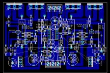
Out of curiosity of how this simple circuit may sound I build it with the layout attached. Currently one channel is working and another is coming. The working channel sounds find but it have a fairly loud "waterfall" noise, not "motorboating" sound, which is noticeable when no music is playing. Pls help to check what is wrong with my layout that causes this.
FYI, I use wire jumper to connect the "unrouted" path, which is VEE, VEE and regulator (7815/7915) to opamp.
Pls advise.
Thanks.

Hi,
Out of curiosity of how this simple circuit may sound I build it with the layout attached. Currently one channel is working and another is coming. The working channel sounds find but it have a fairly loud "waterfall" noise, not "motorboating" sound, which is noticeable when no music is playing. Pls help to check what is wrong with my layout that causes this.
FYI, I use wire jumper to connect the "unrouted" path, which is VEE, VEE and regulator (7815/7915) to opamp.
Pls advise.
Thanks.
Hi there
Thank you for your replies. I finally decided to buy all the components for the dead channel, and to replace everything. It cost me something like 10€. The fixed channel didn't sound as good as the original one, but it was OK and I gave the amp to a friend for his countryside house. Maybe the transistors were of poorer quality.
Here are the schematics that I received from rega. These guys are very friendly and provide a good support. I believe there is no problem posting the diagrams of such an old amp, as it may help passionate people.
FrancoB -> you may have the second version of the amplifier, where they changed the components' numbers (what a good idea). The diagram is almost the same. They just added a couple of fuses.
A question for the experts here: how to adjust IQ ? Where to measure the 15mA ?
Another question: I just bought another brio, almost identical, on a secondhand market. I would like to improve it. Is there anything that can be done, without changing too much the amp? Use better opamps ? Is there a pair of better transistors that could replace the 2955/3055 ? Anything else?
Best regards
Attachments
Originally posted by cosinus
The fixed channel didn't sound as good as the original one, but it was OK and I gave the amp to a friend for his countryside house. Maybe the transistors were of poorer quality.
The transistors probably need to be matched for best quality.
Originally posted by cosinus
A question for the experts here: how to adjust IQ ? Where to measure the 15mA ?
Measure the voltage drop over R13 and R16.
Originally posted by cosinus
Another question: I just bought another brio, almost identical, on a secondhand market. I would like to improve it. Is there anything that can be done, without changing too much the amp? Use better opamps ? Is there a pair of better transistors that could replace the 2955/3055 ? Anything else?
I really wouldn't bother. If you changed the outputs you would probably have to change the driver transistors, and that would mean going to TO-126 or TO-220 packages that wouldn't fit in the PCB.
This amplifier design has an interesting history. It was originally designed by Texas Instruments (i think in Bedford England) as the "Texan" kit for "Practical Wireless" magazine back in the 1970's.
Rega borrowed the design but used more rugged output transistors than the original TIP41/42.
The main feature is that the output stage has some voltage gain which allows the op-amp to run off low voltage supplies.
I believe the original Texan design did not have quiescent current setting adjustment which can give the dreaded crossover distortion.
I googled for Texan amplifier and about the only relevant ref I could find was:
http://www.angelfire.com/sd/paulkemble/sound5.html
which is part of
http://www.angelfire.com/sd/paulkemble/soundindex.html
excellent site which I had not come across before
scroll down to the fifth circuit down on the first page
Like the owner of the brio I am intrigued as to how such an amp would sound with better specified components.
Sgs/thomson have an old little known power buffer, the L149 which could be used as an integrated output stage for an op-amp for those wishing to play with a simple circuit. I am surprised this device is still avaliable from digikey
- Status
- This old topic is closed. If you want to reopen this topic, contact a moderator using the "Report Post" button.
- Home
- Amplifiers
- Solid State
- Rega Brio (one channel dead)