LP12 is still a very good turntable. The Garrard 401 is very similar in style except seems even stonger on rhythm.
The Valhalla hides hum at about - 41 dB. If the capacitors are changed from 47 uF to 220 uF that takes it to - 56 dB. It makes for less wow. The 47uF usually are near life's end now. The whole Valhalla is a nice design. 0.05% THD at 50 Hz. It is as far as I know class A. This is due to only needing 1 watt. The Garrard is more like 30VA ( 301 old style 28VA when rated 16 watt ).
The Valhalla hides hum at about - 41 dB. If the capacitors are changed from 47 uF to 220 uF that takes it to - 56 dB. It makes for less wow. The 47uF usually are near life's end now. The whole Valhalla is a nice design. 0.05% THD at 50 Hz. It is as far as I know class A. This is due to only needing 1 watt. The Garrard is more like 30VA ( 301 old style 28VA when rated 16 watt ).
Back to the opamp driven audio amplifier, I noticed this Denon PMA350SE design posted in another thread and I'm surprised Denon went this way, given their reputation for good sound quality. I'm uncertain of the drive to the discrete power amplifier section though, given the opamp rails are +/- 16V yet it doesn't appear to me least, that drive is taken from there.
I think the simplicity and low cost might make a clone a worthwhile project though")
I think the simplicity and low cost might make a clone a worthwhile project though
Attachments
I think I know that Denon. Had no idea it was like that!. PMA250 is nice.
I don't know where I got this from. I doubt it has been tried. Plenty looks wrong like the biasing ( would be too high ? ). I think the idea of unrestricted output gain with only feedback loop gain limiting is interesting. It should work. On the other hand the Brio defines it's limits before loop feedback applied. If you play with the output gain of a Brio or Texan it is interesting. Mostly it's swapping one virtue for an other. The Texan had high damping factor which high output gain helps. These days we don't think it is of prime importance. Perhaps crossover distortion is reduced if the Texan way. I have doubts about that as using loop feedback instead of local feedback might not get the best result in that regard. Sometimes stability won't allow it. Outputs are like MPSA92/42 ( 0.6 watt package ).

I don't know where I got this from. I doubt it has been tried. Plenty looks wrong like the biasing ( would be too high ? ). I think the idea of unrestricted output gain with only feedback loop gain limiting is interesting. It should work. On the other hand the Brio defines it's limits before loop feedback applied. If you play with the output gain of a Brio or Texan it is interesting. Mostly it's swapping one virtue for an other. The Texan had high damping factor which high output gain helps. These days we don't think it is of prime importance. Perhaps crossover distortion is reduced if the Texan way. I have doubts about that as using loop feedback instead of local feedback might not get the best result in that regard. Sometimes stability won't allow it. Outputs are like MPSA92/42 ( 0.6 watt package ).
I had another look at the Denon design and realised it's a refined version of the old Elektor circuit they presented a few times in different amplifiers, where the drive to the output stage was indeed taken from the opamp supply rails. However, Denon's compensation scheme is something new to me.
Hmm...in your schematic, SOT23 parts are used with up to 300V across the output pair - looks like a suicide mission. I think you would either have a few doubtful mA output or a brief instant of glory there.
If using PZTA42/92 SOT223 versions, there's a small heatsink tab that could help a little - still only 1.5W diss. and anything over 5mA is out of the question at 300V http://www.onsemi.com/pub/Collateral/PZTA42T1-D.PDF
I feel the lack of the local feedback loop ( Q1,2,3,4 ) is a mistake. Having built Texan clones they seem to be unusually stable for an op amp driven design. My hunch is just enough loop and local feedback. The better transistors for 200V ( +/- 100 ) might be 350V types. I will need 250mA which allows for a reactive load. It will give 110Vrms in bridge mode.
Ian. You must have seen the feedback loop as here many times ? With this design the 10pF C1 seems the better place to try something. Many say Cdom (to VAS, TIS) as Douglas Self calls it is the better idea, others like JLH say no. Any thoughts? It would be interesting to think this could be the big deal factor in most designs. As JLH said I think, the power stage has more current to drive it so is the logical way.
Ian. You must have seen the feedback loop as here many times ? With this design the 10pF C1 seems the better place to try something. Many say Cdom (to VAS, TIS) as Douglas Self calls it is the better idea, others like JLH say no. Any thoughts? It would be interesting to think this could be the big deal factor in most designs. As JLH said I think, the power stage has more current to drive it so is the logical way.
I had a look at the full Denon PMA 350. It seems a bit like the mystery circuit I gave. I like the idea of a emitter follower output buffer. The capacitor that joins the two collectors of the previous stage seems a nice idea, I suspect it does a little bit more than the usual.
Nigel-
the 1k emitter resistor and 1k collector resistor of Q1, Q2 only gives unity gain. I suggest that is why the concept is fairly stable and does not need a local feedback loop. In this case.
But the op-amp + power amp idea was taken up with RCA's 120-300W designs where I note they did include a local feedback resistor - which in the diagram of post 103 would be to the centre tap of R9, R10, which obviously could no longer be grounded.
It is possible to achieve stable operation with a two stage (counting the op-amp as one, and the output-stage-with-gain as the other with appropriate feedback loops, as you say, where you can control the frequency response in each.
Global NFB encompassing both in principle would have 12dB/octave roll-off and therefore would be conditionally stable at best, but a phase lead network between the two parts can improve this.
In the end, such a concept is however more difficult to optimise which is why some often design to standard concepts and just go for high voltage transistors.
Regarding the MJE340/MJE350, I have never found an fT spec. but they appear to be 2N3440 generation devices (250-350V) with around 15 MHz ft. I regard that as rather slow, but they might work better in a cascode with faster lower stage devices. I mentioned in another thread of being wary of various BD139/BD140's, but in testing at 1MHz I found ST and ON Semi to be as fast as Philips samples and therefore around 100MHz . There is some concern with BD as a lot of similar devices (e.g. BD239- BD240) were only epi 3MHz, so fakes might be low fT.
A final observation on the TI Texan- originally they appeared to omit a base-emitter resistor on the OP transistors. Another version of the circuit shows they used 220 ohms. With the local feedback resistors (22 ohms) quiescent current stability was said to be stable (I have not worked with this type of amp) and it is reasonable to expect that the bias voltage from a Vbe multiplier would be compensated by the 220 ohms.
For example if the 220 ohms needs 0.6V across it the 22 ohms drops 60mV. The Vbe multiplier should apply -.2mv/C when set up correctly, which gets amplified to -2mV across the 220.
Hi John. I didn't spot the unity gain 1k/1k. That worries me. It means all the work is done by Q3Q4. This must be an op amp rather than small power amp. The biasing suggests class A I suspect.
I read the Texan types only need the Vbe bias to be heat coupled to the emitter follower drivers. Mine were underbiased using biasing resistors and the fixed SMPS 48VDC at about 1.1V between bases. As my use is 95% full output and 50/60 Hz it is enough and no thermal problems. However pushing harder seemed fine.
The only spec on MJE350/340 I read was 6 MHz. I have used the MJE350 as a 330V anode load on a pentode valve ( 160 V static ). The beauty of that idea is both pentode and transistor protect each other. It could not swing hard enough to damage the transistor at 10 mA. It allowed me to see what the pentode could do. As the person who wanted the amplifier was religiously against transistors I used a bootstrap which was every bit as good. This was doubly possible as the amplifier had no loop feedback. It didn't even have local negative feedback as I wanted the gain. It tumbled from 5% THD to 0.2% at 1 watt which is not bad. It drove Quad ESL63's very well. What it used was the cancellation between pentode and semi triode ( 82% triode UL, a spare unitended tap for KT88, me EL34 ). Semi triode gave 30% more gain than fake triode ( G2 strapped ) with no obvious change in THD. I should have spotted the 1k/1k as it is a very typical valve circuit. In valve debates that seemingly perfect idea often said to be imperfect. I have always said if so use a transistor. I bet a T0220FP NPN 400V exists. Many will be 30 MHz. Valve Wizard is my favourite valve site. He claims to be for musicians, his technical side is first class. Far more depth than the Audiophile sites.
The main reason for the use of a CFP output stage was the desire of additional voltage gain - so I think.
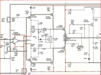
Here is a version of the Brio. Notice it doesn't have the frequecy compensation feedback loop of the Texan. This makes it more likely to protest. The 560/56 gain setting is excessive in my opinion. However it is an exercise is negative feedback I guess. I am a bit surprised the amp can work with this simplicty. I repeat my warnings not to get too careless with choices. TL072 seems a very wise choice. The red bits are the person who posted it choice. I have built this type of amp with an output gain of three and liked it, even two worked.
Looking again I guess C6 R25 are looking to do the same.
Because of the choice of these transistors a darlington emitter follower with unity gain provides clearly the better sonic results by a listening test.
The fact that the max voltage output swing is now defined only by the output voltage of the operational amplifier IC (below +/-15V) is not a real disadvantage (only -6db loss in opposite to the presently used design).
Nevertheless it would be interesting to know, whether one can modify the output circuit in such kind, that while maintaining the genuine topology similar good sonic results could be achieved (maybe other transistors, e. g. from Sanken and/or higher idle current in the driver stage like realised in Linn's Klout - check out page 2 of first PDF attachment in post #52 under
tweaking classic Linn LK1 & LK2 / LK280
Last edited:
The more I played with the circuit the more I liked it. I doubt it has the monotonic distortion Jean Hirage was the champion of.
My brother discovered a simple problem the kit Texans had. Somehow the power was returned via a short piece of screened cable. I think this was an accident that went into production. He put this right and found much instability resolved.I always remebered Terry at Rega's face when I said " that's a Texan ". His reply was " no one else had noticed that. Roy had wanted the simplest design that he could manipulate. This was the mk1 Brio's. I suspect my dislike of that Brio was the PSU was too small. I think I was collecting some parts to do a repair iof a Brio. We went in my friends Lancia Integrale ( 8V ). It was about 1988 I think. The new Rega factory hadn't been in use long.I think I also saw pick ups being made and wiring a Rega arm. I set some arm bearings.
My brother discovered a simple problem the kit Texans had. Somehow the power was returned via a short piece of screened cable. I think this was an accident that went into production. He put this right and found much instability resolved.I always remebered Terry at Rega's face when I said " that's a Texan ". His reply was " no one else had noticed that. Roy had wanted the simplest design that he could manipulate. This was the mk1 Brio's. I suspect my dislike of that Brio was the PSU was too small. I think I was collecting some parts to do a repair iof a Brio. We went in my friends Lancia Integrale ( 8V ). It was about 1988 I think. The new Rega factory hadn't been in use long.I think I also saw pick ups being made and wiring a Rega arm. I set some arm bearings.
- Status
- This old topic is closed. If you want to reopen this topic, contact a moderator using the "Report Post" button.
- Home
- Amplifiers
- Solid State
- Rega Brio (one channel dead)