Hi Guys,
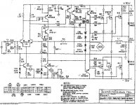
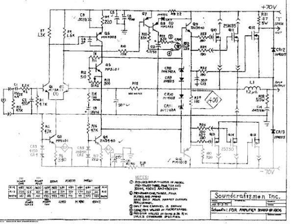
I bought a PSR800 not working. While checking it out I found it had rail voltage on the right output. I opened it up and found the 2N3440'S and the MM4003'S were litererally falling off of the board. I have now replaced all of them as well as all of the 1N4150 diodes. I'm still reading rail voltage on the right side. I'm attaching the schematic in hope that you guys might give me some direction as to where to look for the problem.
Thanks, Terry
P.S. I reading negative volts on the output if that helps.
Attachments
Hi JC,
Thanks for replying. When you say replace the devices are you talking all of them?
I was thinking the same thing about comparing the readings from the two channels, as a matter of fact I was trying to do that last night, but they are layed out totally differently on the board so it is difficult to trace each of them down to compare. there is no silk-screening on the board so I have to try to follow the foil traces and track them down. That's very time consuming.
I was hoping that there were a couple of key places that the rail voltage would be likely to transfer through and I could start looking there. There are a few symbols on the schematic that I don't understand, like the
---> >--- symbols. Are those just direction arrows or do they represent a component? I know I'm probably too green at this to tackle this project but I was hoping that with your guys' kind help I might get it fixed and learn something in the process.
Thanks again, Terry
No, I meant the ones you found loose, they are the VAS and the current source to drive the VAS.. if the VAS is bad it will most likely pull the output to the rail. Looking at the circuit, you may also wish to check the VBE multiplier (the transistor near the potentiometer labelled "BIAS")
It's also definately worth testing the MOSFETS, one of them could well be short due to whatever caused the VAS/driver stage transistors to unsolder themselves.
edit: I may have misunderstood when you said " I have now replaced all of them" to mean "I resoldered them into place correctly" and not "Replaced with brand new parts".
edit 2: Yeah, those funny arrows just look like arrows showing the direction of current flow through the output stage. Bit bizarre if you ask me... but...")
It's also definately worth testing the MOSFETS, one of them could well be short due to whatever caused the VAS/driver stage transistors to unsolder themselves.
edit: I may have misunderstood when you said " I have now replaced all of them" to mean "I resoldered them into place correctly" and not "Replaced with brand new parts".
edit 2: Yeah, those funny arrows just look like arrows showing the direction of current flow through the output stage. Bit bizarre if you ask me... but...
Thanks Jaycee,
Yes, when I said I replaced them I meant I bought new parts and replace all of the 2N3440's and MM4003's, although I replaced the MM4003's with 2N5416's since they don't seem to make the MM4003's anymore. They weren't just unsoldered, the leads were actually eaten away by corrosion. The same with a couple of the 1N4150's so I replaced all of those.
As to the VBE, are you refering to Q5?
What's the best way to test the MOSFETs for a short? Diode test? Ohm?
Same question for the MPSL01's How best to test them in circuit?
I notice on this amp that the cases or the T-03 MOSFETS are all connected to their perspective heatsinks. Then the heatsink is connected to the PCB.
Weird thing about those little arrow looking symbols is that they are all pointing away from the MOSFET that they are associated to. If that is representing current flow, wouldn't there need to be at least one lead flowing toward the MOSFET? Maybe it represents a plugin connection. I see the same symbol at the red clip LED. That part has plugin leads. I don't think the MOSFETs plugin on this amp but maybe they did when this schematic was drawn.
Also, any idea what the diamond symbols are representing? The ones with the .400 and 0.7 inside?
Thanks, Terry
As to the VBE, are you refering to Q5?
Yep, that's the one.
What's the best way to test the MOSFETs for a short? Diode test? Ohm?
Ohm test as far as I know - I'm pretty sure there was a thread a while back on here about how to test MOSFETS.
Same question for the MPSL01's How best to test them in circuit?
In circuit is probably not a good idea. Test out of circuit with a diode test. Main thing to check is that there is conduction only one way between collector/emitter.
I notice on this amp that the cases or the T-03 MOSFETS are all connected to their perspective heatsinks. Then the heatsink is connected to the PCB.
Hmm, that sounds rather unreliable to me, but a good way to do without the heatsink insulators.
Weird thing about those little arrow looking symbols is that they are all pointing away from the MOSFET that they are associated to. If that is representing current flow, wouldn't there need to be at least one lead flowing toward the MOSFET? Maybe it represents a plugin connection. I see the same symbol at the red clip LED. That part has plugin leads. I don't think the MOSFETs plugin on this amp but maybe they did when this schematic was drawn.
Aha, yes, you could be right there. Whatever they are they're not mega important though.
Also, any idea what the diamond symbols are representing? The ones with the .400 and 0.7 inside?
I would say these are indications of what the voltage should be across the part in question.
I did think of a quick test for the outputs being short. If you pull Q9 and Q12 out of circuit, there should be no voltage on the output at powerup. If there is, you have a shorted 2SJ50.
I would say these are indications of what the voltage should be across the part in question.
Cool, I'll check that. On second thought, that would be at full power. I better wait until I resolve the other problem before run this thing back up to full power.
I did think of a quick test for the outputs being short. If you pull Q9 and Q12 out of circuit, there should be no voltage on the output at power up. If there is, you have a shorted 2SJ50.
OK I see that. Although, if that were the case then my problem would have to be the MOSFETs wouldn't it?
Is there nowhere else that the rail power could be getting to the output?
Let me make a couple of observations and then ask a couple of questions.
When I measured the output voltage at the speaker terminals, I hooked up the red lead to the red speaker terminal and the black to black. I read -65V. This made me believe that it was the negative rail that was bleeding through.
Is this a fair assumption?
Also when I follow the negative rail on the schematic it appears that the only places that the negative rail connects to the output are at the MOSFETs Q13 & Q14 and through Q3 and Q2.
I just thought of one other thing that may or may not be important. As soon as power is applied, the red clip indicator lights up on the bad channel.
Blessings, Terry
Cool, I'll check that. On second thought, that would be at full power. I better wait until I resolve the other problem before run this thing back up to full power.
I see you have a variac from earlier posts. The good old lightbulb trick might work better for this, as it's limiting current.
OK I see that. Although, if that were the case then my problem would have to be the MOSFETs wouldn't it?
If you remove both driver transistors and you're still getting rail voltage then yes, one or more MOSFETS are bad.
Is there nowhere else that the rail power could be getting to the output?
From the schematic, no. Check the PCB for shorted tracks just in case though.
When I measured the output voltage at the speaker terminals, I hooked up the red lead to the red speaker terminal and the black to black. I read -65V. This made me believe that it was the negative rail that was bleeding through.
Is this a fair assumption?
Correct. The black speaker terminal will be connected to GND of the power supply, so if youre reading -65V then that's the negative rail voltage on your output.
Also when I follow the negative rail on the schematic it appears that the only places that the negative rail connects to the output are at the MOSFETs Q13 & Q14 and through Q3 and Q2.
Not through Q3 and Q2 - the only connection to the output is via Q2's base... it's unlikely thats the cause, Q2 would probably burn up if it was short enough to cause rail voltage to flow through it to the output.
I just thought of one other thing that may or may not be important. As soon as power is applied, the red clip indicator lights up on the bad channel.
That's just the clip detector seeing the stuck rail voltage as a clip.. So at least the clipping detection works
OK, I pulled the Q 12 and Q9. no change still voltage on the output. So I disconnected everything that connected up to either the + or the - rail and still voltage on the output. I thne checked and the voltage is on the heatsink. After looking more closely to the schematic it appears that the heatsink is what is connected to the output. Now I don't understand MOSFETs too well so this may be a dumb question. Is it possible that a MOSFET that is not switched on could allow the rail voltage to pass. When I pulled Q9 & Q12 on the good channel, I read rail voltage there too. After I soldered them back in it dropped back down.
Is this possible?
If not then I guess my MOSFETs are toast.
Blessings, Terry
Is this possible?
If not then I guess my MOSFETs are toast.
Blessings, Terry
W
No variac please.
As someone else said, use a lightbulb, try 75W~100W.
The little arrows indicate connector plug contacts.
Heatsink at speaker out potential.
All small signal transistors with gold leads must have the solder wicked dry, and then replaced. 4% silver if possible.
Measure voltage at Q3 collector, should be -0.7V or so.
Check collector voltage on Q6 and Q4, Q6 should be about 3V higher.
Hmm OK... perhaps MOSFET gates are sensitive enough to pick up nearby charge and switch on when the drivers are removed... pity, that wouldve been an easy test
You could try unsoldering the drivers and soldering 2 wire links from the emitter hole to ground, this would make sure the MOSFETS are definately off. I'm not too sure about this though - anyone else care to comment ?
It might be worth checking neither of the 1N4005 catch diodes have blown short and thats whats putting rail voltage on the output.
Also, you could check (with the power off and caps discharged) if theres any continuity between the heatsink and the -70V rail when powered off - if there is thats a sure sign theres a shorted device.
Thanks guys,
I'll check the things you've suggested. I put it away for a couple of days to let my head settle. To many scenarios wheeling around in there right now. I'm forgetting what I've tried and what I haven't. I'll pull it back out on Monday and give it another go.
The traces on the board are a little fouled up. Three of them so far just went away at the pad when I tried to resolder them. I've had to put in wire links. I hope this isn't going to be the case throughout. I may just have a box of parts here. Hope not.
I'll let my head clear a bit over the weekend and dig into this again on Monday.
Thanks so much for all the help. I'm learning a lot if nothing else.
Blessings, Terry
Each MOSFET should be insulated from the heatsink with a mica washer and white grease. Can you see the mica washers underneath each MOSFET?
The case of the MOSFET is the source, the two pins are gate and drain.
You seem to be observing drain voltage on the heat sink and at the output.
Check the wiring to the MOSFETs on the back side of the circuit card and the back side of the MOSFET mounting socket. Voltage to the gates should be around .5-.7 volts, polarity depending on channel. The wiring connection to the drain tab is the rail voltge. The source voltage should only be that of the output AC signal.
The --> symbols indicate how the wiring is run over or under something. It relates to the wiring layout and is not an electrical symbol.
You could pull the 2SJ50 mosfets and see if that stops the -65VDC from appearing on the heat sink itself and at the output. The 2SJ50 is a P-channel device and is located on the negative side of the circuit. Generally a MOSFET will fail "open" but if one were shorted to allow drain voltage to get to the source pin then you would see rail voltage at the output.
You would only see rail voltage on the sink if it somehow wiring to the drain connection got shorted to the sink. The sink should be insulated from any circuit connection.
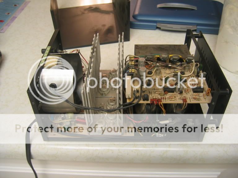
This is actually a picture of my good PCR800 but they look the same.
As you can see, the heatsink mounts to the PCB. The MOSFET's pins pass through the Heatsink and solder directly to their respective traces on the board. There are no sockets. I checked both PCR800s that I own and in all cases the MOSFET cases are connected to the heatsink without any washers, only grease. I did a continuity test on each MOSFET and they all are a direct connect to the heastink. The mounting bolts for the heatsink are what is soldered to the output traces. There is no other way that the MOSFET case is connected, only though the heatsink. I will pull the MOSFETs one at a time and see if the voltage goes away. I can't really check the voltage at the other two pins right now because I don't want to run it at full voltage again until I get this figured. I just glad I didn't touch that heatsink when I had it a full voltage. Also, I had said there was rail voltage at the output but it is actually less than full rail I don't remember exactly how much less but it is some. I will check that as well and report back.
It would take some special work to make a Hafler board work in one of these.
Truth is, I think these Soundcraftsmen amps sound better than Haflers. At least to my ears they do.
Thanks for all your help. I will keep you abreast of what I find when I pull the MOSFETs.
Blessings, Terry
"Each MOSFET should be insulated from the heatsink with a mica washer and white grease."
Why?
The extra thermal resistance would require a larger heatsink.
" I had said there was rail voltage at the output but it is actually less than full rail I don't remember exactly how much less but it is some"
Fine and dandy. How much? I inferred it was stuck to one rail. Is it like 4~5V or so? Replace C9.
Hey thanks guys.
I will replace C9 and see what I get, before I start pulling the MOSFETs. I had thought about replacing all the 1N4005's but I measured them with the diode test setting on my multi-meter and they were all very close to each other. I'm trying to not do any more unsoldering/resoldering than I have to since the traces seem to be so weak. I've already had to put in three jumper wires because of the traces receding.
I agree that having the heatsinks "hot" is a little more dangerous, but these are enclosed inside the case and in a healthy amp they only carry the output current which would be as safe as touching the speaker wires.
I'll rig up a light bulb to do the rest of the testing. I have been using my Variac set at about 12V so far, but if you guys think that is risky I'll stop doing that. Question; with the light bulb setup, do you go ahead and run it at 120v? Can I still use the Variac in conjunction with it so that I'm not running that high of voltage? I'd hate to get shocked because I happened to brush the heatsink.
Thanks again, Terry
- Status
- This old topic is closed. If you want to reopen this topic, contact a moderator using the "Report Post" button.
- Home
- Amplifiers
- Solid State
- Soundcraftsmen troubles