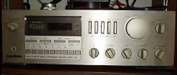
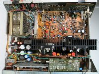
Made in the eighties by Gradiente, started with hi speed transistors.
The first one to use those "hi speed" devices here.
Now a days it is already searched by native audiophiles.
Produce a warm (a little mufled) sound, with good dinamics and temperature good to keep you coffee hot....just put is over the amplifier...do not forget the dish to protect from coffee leakage to circuit.
You cannot find to sell....the ones that have do not intend to sell..... when you find, people is asking more than 500 dollares.
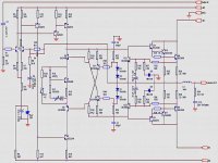
here is schematic, a friend send me, completely free to you all.
be happy.
Carlos
The first one to use those "hi speed" devices here.
Now a days it is already searched by native audiophiles.
Produce a warm (a little mufled) sound, with good dinamics and temperature good to keep you coffee hot....just put is over the amplifier...do not forget the dish to protect from coffee leakage to circuit.
You cannot find to sell....the ones that have do not intend to sell..... when you find, people is asking more than 500 dollares.
here is schematic, a friend send me, completely free to you all.
be happy.
Carlos
Attachments

Rodolpho, nice to meet you. Please, send your personal
Adress, your mail adress to my Email adress:
nanabrother@yahoo.com
So, i will be able to send you the PDF.
That PDF file, has another forum text under...i think not delicated to publish here with that thing there.
So, it is small, less than 20K, and have the Adobe magnificent quality, but i do not want to publish here that file.
Having you adress, with pleasure, imediatelly i will send you.
regards,
Carlos
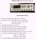
The output transistor is a 150W dissipation unit
And it is alike the 5200 famous transistor....160 Volts maximum and 16 amperes maximum current.
To be safe, using 8 ohms loads, better to use the output voltage with plus and minus 35 volts and 40 volts plus and 40 volts minus to power input stages.
regards,
Carlos
And it is alike the 5200 famous transistor....160 Volts maximum and 16 amperes maximum current.
To be safe, using 8 ohms loads, better to use the output voltage with plus and minus 35 volts and 40 volts plus and 40 volts minus to power input stages.
regards,
Carlos
I found the schematic in this forum : http://htforum.com/vb/ . This is in portuguese, use the www.altavista.com traductor for view in english...
Thanks.
Thanks.
Carlos, Mod_Evil,
thanks for posting this one.
I never heard of Gradiente, even an original name.
The parts and triple output looks quite attractive.
I still have loads of the 968/970/2238/2240/1095/2565 devices,
yet another one i will have to try.
Hope you do not object if i add a connection between the 970 and 2240.
jacco vermeulen said:Carlos, Mod_Evil,
thanks for posting this one.
I never heard of Gradiente, even an original name.
The parts and triple output looks quite attractive.
I still have loads of the 968/970/2238/2240/1095/2565 devices,
yet another one i will have to try.
Hope you do not object if i add a connection between the 970 and 2240.
Hi, i'm benniner in audio, Carlos can anwer your question.
Thanks for reply
At a first glance at the schematic I have no idea how this complicated bias control works. Could anyone help? It the first time I've seen it done like this.
I don't (or haven't) understand it either. I think it is a variation of biasing scheme discussed here: http://www.diyaudio.com/forums/showthread.php?postid=598344#post598344
Lumanauw, the bias control. constituted by Q6, with the help of Q5 and Q8...
those colector to emitter junctions, are working as resistors.... alike three resistors and series, of coursin, having an adition result that can be imagine, as a single one. Those three transistors work together, designed, calculated, to maintain a good voltage to the upper and lower triple darlington output devices... three transistors, connect as one single darlington unit, needing 3 X 0.6 Volts each one of them to conduct good current. So, those junctions, working as resistors, are there only to develop voltage , as consequence of the current that will cross both three colector to emitter junctions, voltage produced, enougth to turn on the output transistors. Those three transistors are on....producing some ohms of resistance each one of them...the main unit is the central one, where you adjust the stand by bias current, adequated to the ammount of class A you want....i imagine that current, adjusted in RV1,and measured in the positive and negative rail, without audio in the input, may be something around 500 miliamperes...to produce some watts of class A operation
those three transistors, connected as triple darlington need 1.8 Volts minimum to upper rail and 1.8 Volts minimum to lower railto have a good current crossing colector to emitter junctions....so, the voltage developed over that bias control resistor, have to be 3.6 volts, considering plus 1.8 added to negative 1.8..... so, if you decided to make a very simplified circuit, you have to produce 3.6 volts over some resistor... and the current will be the designed, calculated current that may cross Q4 and Q9....so.....if you know that current.... the one is crossing R15, Q4, Q5, Q6, R10, R8, Q9 and R18, you can calculate the resistor that can substitute those three bias transistors, the main one (Q6) and the auxiliary others (Q6 and Q8).... knowing the voltage you need over them, transformed in one single resistor (3.6 Volts) and knowing the current...you can enter ohms law and calculate your resistor...and will work very good...but will compensate nothing, adjust nothing, beeing a normal resistor.
When the current cross the VBE multiplier colector to emitter junction, it tuns and heat sensitive device, reducing its colector to emitter resistance when the junction over heat, the more heat, the less the resistance.
So, can be understood as something that we can call a NTR, negative Termistance resistor, or something called alike.
When you have some reduction in resistance value, as a consequence, the voltage developed over this resistor leads.
As you know, the same thing happen from colector to emitter in the VBE multiplier transistors...beeing a single one transistor or many.... since receive heat, their internal resistance diminish when over heated...so, voltage reduces, and that voltage decreasing, reduce the current in the output triple darlington...some automatic correction as you know.
But there's a simple modification, you can see two more transistors up and down the normal design of VBE multiplier, you can find them over and under the normal circuit, they are Q5 and Q8. those transistors may be not mounted in the heatsink, i am not sure...have to think about that (you can think too and help old charlie)... those transistors receive DC informations from another circuit, the one you see with many diodes.
Q5 and Q5 are always conducting, presenting a small resistance from colector to emitter, and they are mounted in series with the main VBE multiplier... all them together can be understood as a single resistor, result of the three colector to emitter junctions resistance added together in a series form.
those resistances together.. the Q5, Q6 and Q8 resistances, made in series, will be working as one single resistor, this single one adjusted to some watts of class A operation..... and big current flowing. in the output transistor.... but, when you increase this amplifier volume, the audio AC voltage, superposed to Q14. DC base voltage, will be transfered to Q11, the positive going audio pulses, that can increase the 1.8 volts expected there, will make this transistor operate and will increase bias at Q8, this one, as a result will reduce its colector to emitter resistance...so, the series resistors, formed by the Q5,Q6 and Q8 colector to emitter resistances, will diminish..... that result of those series resistor reduction of resistance, will reduce the bias voltage, and the amplifier will not work in class A anymore, going to class AB operation....not only the audio positive going alternated signals will change the first transistor (from the triple darlington) base voltage, the reduction in resistance will start the bias reduction to positive going signals....but also, same thing will happen to negative going audio signals, this way, they will make Q7 and Q5 operate......i imagine that this circuit do not control only bias, also those distortions that produces positive cicle bigger than negative (or the opposite) will be corrected too.
Well, do you think this is confused...hehe...i think so, and a big effort to teach something that i am already learning...sorry if big mistakes here....please!...more experienced guys can enter and correct, and complete the needed informations.
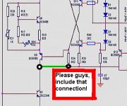
Some line was missed in the schematic, not only in my JPEG copy, but also in the PDF.
I am posting the point to include a conection, and those points, to be joined, are marked with green color.
regards,
Carlos
those colector to emitter junctions, are working as resistors.... alike three resistors and series, of coursin, having an adition result that can be imagine, as a single one. Those three transistors work together, designed, calculated, to maintain a good voltage to the upper and lower triple darlington output devices... three transistors, connect as one single darlington unit, needing 3 X 0.6 Volts each one of them to conduct good current. So, those junctions, working as resistors, are there only to develop voltage , as consequence of the current that will cross both three colector to emitter junctions, voltage produced, enougth to turn on the output transistors. Those three transistors are on....producing some ohms of resistance each one of them...the main unit is the central one, where you adjust the stand by bias current, adequated to the ammount of class A you want....i imagine that current, adjusted in RV1,and measured in the positive and negative rail, without audio in the input, may be something around 500 miliamperes...to produce some watts of class A operation
those three transistors, connected as triple darlington need 1.8 Volts minimum to upper rail and 1.8 Volts minimum to lower railto have a good current crossing colector to emitter junctions....so, the voltage developed over that bias control resistor, have to be 3.6 volts, considering plus 1.8 added to negative 1.8..... so, if you decided to make a very simplified circuit, you have to produce 3.6 volts over some resistor... and the current will be the designed, calculated current that may cross Q4 and Q9....so.....if you know that current.... the one is crossing R15, Q4, Q5, Q6, R10, R8, Q9 and R18, you can calculate the resistor that can substitute those three bias transistors, the main one (Q6) and the auxiliary others (Q6 and Q8).... knowing the voltage you need over them, transformed in one single resistor (3.6 Volts) and knowing the current...you can enter ohms law and calculate your resistor...and will work very good...but will compensate nothing, adjust nothing, beeing a normal resistor.
When the current cross the VBE multiplier colector to emitter junction, it tuns and heat sensitive device, reducing its colector to emitter resistance when the junction over heat, the more heat, the less the resistance.
So, can be understood as something that we can call a NTR, negative Termistance resistor, or something called alike.
When you have some reduction in resistance value, as a consequence, the voltage developed over this resistor leads.
As you know, the same thing happen from colector to emitter in the VBE multiplier transistors...beeing a single one transistor or many.... since receive heat, their internal resistance diminish when over heated...so, voltage reduces, and that voltage decreasing, reduce the current in the output triple darlington...some automatic correction as you know.
But there's a simple modification, you can see two more transistors up and down the normal design of VBE multiplier, you can find them over and under the normal circuit, they are Q5 and Q8. those transistors may be not mounted in the heatsink, i am not sure...have to think about that (you can think too and help old charlie)... those transistors receive DC informations from another circuit, the one you see with many diodes.
Q5 and Q5 are always conducting, presenting a small resistance from colector to emitter, and they are mounted in series with the main VBE multiplier... all them together can be understood as a single resistor, result of the three colector to emitter junctions resistance added together in a series form.
those resistances together.. the Q5, Q6 and Q8 resistances, made in series, will be working as one single resistor, this single one adjusted to some watts of class A operation..... and big current flowing. in the output transistor.... but, when you increase this amplifier volume, the audio AC voltage, superposed to Q14. DC base voltage, will be transfered to Q11, the positive going audio pulses, that can increase the 1.8 volts expected there, will make this transistor operate and will increase bias at Q8, this one, as a result will reduce its colector to emitter resistance...so, the series resistors, formed by the Q5,Q6 and Q8 colector to emitter resistances, will diminish..... that result of those series resistor reduction of resistance, will reduce the bias voltage, and the amplifier will not work in class A anymore, going to class AB operation....not only the audio positive going alternated signals will change the first transistor (from the triple darlington) base voltage, the reduction in resistance will start the bias reduction to positive going signals....but also, same thing will happen to negative going audio signals, this way, they will make Q7 and Q5 operate......i imagine that this circuit do not control only bias, also those distortions that produces positive cicle bigger than negative (or the opposite) will be corrected too.
Well, do you think this is confused...hehe...i think so, and a big effort to teach something that i am already learning...sorry if big mistakes here....please!...more experienced guys can enter and correct, and complete the needed informations.
Some line was missed in the schematic, not only in my JPEG copy, but also in the PDF.
I am posting the point to include a conection, and those points, to be joined, are marked with green color.
regards,
Carlos
jacco vermeulen said:Hope you do not object if i add a connection between the 970 and 2240.
Of course i will,Coronel Carlos.

Attachments
- Status
- This old topic is closed. If you want to reopen this topic, contact a moderator using the "Report Post" button.
- Home
- Amplifiers
- Solid State
- A good Brazilian Amplifier, class A switching to AB in hi power