It is NOT Possible to post a Resistance Value, as This adjustment "corrects" for various Tollerances in Transistors and other parts. It will change from one to the next.
A PCB Layout is now Available at: http://www3.telus.net/chemelec/Projects/Projects.htm
Look at the PCB ...., Article
My board has Meter Connection Pads for a Meter to set the 1.8 Ma. After Set, Put a Jumper in there.
A PCB Layout is now Available at: http://www3.telus.net/chemelec/Projects/Projects.htm
Look at the PCB ...., Article
My board has Meter Connection Pads for a Meter to set the 1.8 Ma. After Set, Put a Jumper in there.
Current of the relay
I have made some calculations and i want that you confirm my suspects. The current that the relay may support is I^2=P/R so if whe use speakers of 4 ohms the aprox max current for the relay is 8.6 Amps? So we need a relay of 8 amps?
Another little question, what width of wire do you use to drive 6-8 amps in the pcb?
Thks a lot, whising to know early about it
Pichichus
Yes the output stage is mounted outside the pcb, but this dc protection contens the relay. I will use one for pcb, so i've to cross the relay throught pcb. I think that the courrent that the switch of the pcb suports is aproximately maximum 8 amps. Isn't?
The width for 8 amps must be too large... so i'm considering to mount out the realy.
But, this 8 amps, are well calculated? can you help me? Use I a relay for 8 amps?
Thks
The width for 8 amps must be too large... so i'm considering to mount out the realy.
But, this 8 amps, are well calculated? can you help me? Use I a relay for 8 amps?
Thks
I haven't actually built this amp and I didn't look that closely at the Relay protection circuit, But it Does NOT Mount on the main circuit board. It is a Seperate circuit.
If you want More Help, Email me Directly at: chemelec@hotmail.com
Put "Electronic M250" in the "Subject Line".
It would also help me to help you if you send me a picture of the Schematic of this relay circuit and how it connects to the amp.
Than I can probably help you a lot more. I could maybe also do a board for the relay.
Take care..........Gary
Project
I'm currently going to school at SAIT in Calgary, AB. I'm thinking of building this amp for my final project.
Has anyone gone to SAIT and built this amp for their final project and if you have how did it work for you?
Did you have enough time to complete it?
Could you find all the necessary parts easily?
 i just want to ask if this amplifier could drive until 6 hours continous duty?how does it sounds when it comes to bass ?
For guys who have built the speaker protection unit :
I built the protection unit for another amp but this thing is behaving really crazy. The contact closed with no delay at all. When a 3V dc is applied to where the speaker is suppose to go, it won't trip. Can anyone have come comment on this ? It's now lying peacefully on top of my monitor.
I built the protection unit for another amp but this thing is behaving really crazy. The contact closed with no delay at all. When a 3V dc is applied to where the speaker is suppose to go, it won't trip. Can anyone have come comment on this ? It's now lying peacefully on top of my monitor.
I have Misplaced the Origional Schematic. If you send it to me, I'll correct the error if there is one.
But I Also Don't see any difference between your two Posts.
chemelec@hotmail.com
PLEASE Put the Words "Electronic M250" In the Subject Line.
Take care..........Gary
But I Also Don't see any difference between your two Posts.
chemelec@hotmail.com
PLEASE Put the Words "Electronic M250" In the Subject Line.
Take care..........Gary
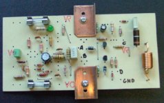
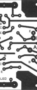
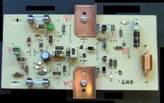
Hi Dragance007, Did you put T8 and T9 on the Board?
They should show on the Parts Side where you have the Heat Sinks, Or did I do them Backwards?
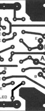
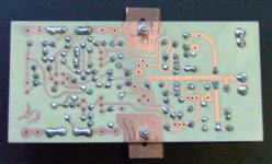
How About This Parts Overlay, From your Picture.
I also Edited that Jumper and Fixed it.
Take care.............Gary (Chemelec)
They should show on the Parts Side where you have the Heat Sinks, Or did I do them Backwards?
How About This Parts Overlay, From your Picture.
I also Edited that Jumper and Fixed it.
Take care.............Gary (Chemelec)
Attachments
Dragance007, I have 4 of these Origional boards, with that Error.
Since this error is Fairly Easily Corrected and Because of your Feedback on this, If you want Two of these Boards, I will send them to you for Totally Free, including the postage cost.
Once I know if you Do or Don't want them, I will than Give away the remaining 2 or 4 boards to one or two lucky persons, ALSO TOTALLY FREE.
(FURTHER DETAILS WILL BE COMING IN THE NEAR FUTURE.:
(NOTE: I Especially Designed, Etched and Drilled these 4 boards for another Person, But he Never came through with the money.
These kind of guys "CHEESE ME OFF", But on the other hand, they are Useable Circuit Boards and I hate to see them go to waste.)
Take care..........Gary
- Status
- This old topic is closed. If you want to reopen this topic, contact a moderator using the "Report Post" button.
- Home
- Amplifiers
- Solid State
- Another amp