Hello I have a question for all you guys....I would like to build an amplifier for a subwoofer and I found Marcus one.I would like to ask how do those MJ sound in bass?Because from my little experience I understood that these transistors do matter in the quality of bass.Some one who had used some old audio KD502/KD503 but they don't build that anymore....So please help")
is being addicted to power really such a bad thing? i mean, i think those suffering from power withdrawals can be attributed to some of the worlds greatest inventions. maybe I am off my rocker though, seems to me Tesla was probably afflicted by such a disease.
sorry, back to the subject at hand, I actually do have a couple questions in case anyone feels like answering questions today....
1. I noticed this amp does not have a output decoupling capacitor, I imagine this is because DC would be the least of the output speakers worries if it were not heavy duty enough to handle the power. Is that the case, or am I not seeing something.
2. I am attempting to build car amps at the moment so if I do end up incorporating any of these concepts into my amp they will only be similar to this design. but assuming the amps are fairly close to the same, where would the best place to put a crossover be? I am thinking either highpass/bandpass for multiple mid-range speakers, or lowpass to drive a sub. I have a few sample chips I ordered free online that do resistor-controlled active filtering, that might complement a opamp based gain control, is there any reason thats a bad idea? or should i just use a massive coil at the output, thereby avoiding possible noise picked up and amplified further along than where the active filter would be placed.
3. this one is not specific to this amp design but more a general amp question, why do many consumer (even high-end) audio amps use plastic case transistors when it seems a can transistor would dissipate heat more effectively? does this have to do with noise or signal quality, or is it a result of cutting costs? also are there any transistors that are similar to the discontinued toshiba lines? i have heard they are very good and have found them to be difficult to obtain, but I imagine there has to be something still in production that meets or exceeds their performance or they would probably still make them
ok thats all for now,
thanks everyone who posted in this thread, it contains a ton of info I had been looking for.
NICK
OK so i read a little more of Marcus's site and see that he is just not showing his protection method. that answers my first question.
and regarding the third question, I came across an old transistor tester that uses a variable-level staircase generator to drive the base, and then the collector supply is a sawtooth that probably is whats left after the timing cap for the staircase, well that probably doesnt make any sense, maybe I will come up with a better way to describe it or maybe i will just take a picture of it.
the transistors i bought for use in my next amp are MJ15022 and MJ15023, I figured they were probably better than 3055 and 2955 for audio use. however when compared with the 2SC3281 and 2SA1302 they dont hold a candle to the toshibas. I got 2 each of the toshibas out of an old sony receiver.
the toshiba waveform looks very precise and fairly unaffected by the base current adjust, and the MJ1502x are completely different at one end of the adjustment range than when at the other end.
when i did hook up both transistors completely paralleled (pnp and npn b-b e-e c-c), the MJ15022 looked as though they amplified the majority of the range (balanced each other out) but the 2SA1302/2SC3281 were still way more accurate. I wonder if the voltage drop was just very low, or if the current given by the tester was just not enough to notice any difference in performance of the plastic case transistors.
well thats all for now, of the questions i had previously i really only have one now, why would someone choose a coil as a low-pass filter over using an active filter, and vice versa? i think the coil would dissipate some of the power out of my output and I would really like a volume control anyway(my volume control idea uses opamps) so I am leaning in the direction of the active filter at the moment.
thanks
SeaNICK
How consumer electronics is designed...
Keep snipping parts out till the thing stops working then go back one step.Morello said:Hello!
I agree with Mr Pass.
I have never used L//R-networks in series with the output.
\Morello
Great amp, but a few operational questions
Hey I have to congratulate Marcus on his amp. I completed it yesterday and have been performing tests on it. It has an extremely fast response and no phase shifts until you get to over 20kHz which doesn’t matter any way. When I get all the works finished I will post my designs for the layouts and the ‘soft on’ relay circuit.
My question is what the input range of the amp is. I have found that it takes about 4.3Vp-p to make the output start to clip. This seems high. Is there anyway other than adding an AGC (Automatic Gain Control) circuit to the input so that I can use it with standard 1Vp devices?
My second question will possibly be answered by the first question. There is one pot in the circuit that is attached to the base driver transistors. I have found that it doesn’t seem to change the output… What does it do?
Here is the link again so you don’t have to go back to the first post.
http://www.astro.uu.se/~marcus/private/m250.html
Thanks Again Marcus
P1 in the circuit is the pot for the bias generator (or VBE multiplier). This sets the voltage bias for the OPS. Ideally the associated transistor should be mounted on the heatsink of the OPS as close as possible to one of the output transistors. The only noticble difference that you would tell by ear when varying this pot would be some crossover distortion. Usually easiest to hear in the high end. It should be set to the point just past where the x-over dist. is not noticable if tuning by ear, or set via a multimeter according to the reqired bias point (~2.6 Volts for an EF design)
-Dozuki
-Dozuki
Ok so i've got that taken care of.... BUT
So after a hard night of testing at 8 ohms i decided to try 4 as his specs say it can handle it. So it was doing fine, although running quite warm untill i went to low frequency. I hit like 20-30Hz and both fuses blew.... Now this was a Sine wave and not a peak or one shot low freq noise. I don't imagine amps are designed to put out that kind of load as most audio dosent sit at one perticular frequency. If anybody knows if this is something that is common or if i have something wrong with my configuration then please let me know. I WAS running 6A fuses on the + & - sides over a 4 ohm load with +&- 55V rails. granted this is what he has stated in his schematic. I can do the math and see that it was over 13A peak current. but i was wondering if that means that i just shouldnt drive a 4 ohm load or if i should just get bigger fuses !
!
Thanks for all your help
So after a hard night of testing at 8 ohms i decided to try 4 as his specs say it can handle it. So it was doing fine, although running quite warm untill i went to low frequency. I hit like 20-30Hz and both fuses blew.... Now this was a Sine wave and not a peak or one shot low freq noise. I don't imagine amps are designed to put out that kind of load as most audio dosent sit at one perticular frequency. If anybody knows if this is something that is common or if i have something wrong with my configuration then please let me know. I WAS running 6A fuses on the + & - sides over a 4 ohm load with +&- 55V rails. granted this is what he has stated in his schematic. I can do the math and see that it was over 13A peak current. but i was wondering if that means that i just shouldnt drive a 4 ohm load or if i should just get bigger fuses
!Thanks for all your help
Dragance007 (powerholic again)
Dragance007 had also built the M250 power amplifier. I run it on the 2x45 v...i have no other tranformer so i use that one. it has 200VA. I did make 150w sine wave on 4 ohm load. but now i run it on the 2 ohm load(it works fine)....if anybody could tell me can it work on 2 ohm load and what power can it give vith +/- 55 v rails it would be super.
P.S. I admire the constructor of this amp it is something !!!
Dear all,
Thanks to Drafance77 and TJtsj for your input!
I have not been doing any audio stuff for some time now, but it's very interesting to hear from people who have actually tried the design.
For TJtsj, I'm not sure what caused your fuses to blow. Of course, the fuses blow if the output transistors break down, but if the amp itself
is intact my guess would be that the bias
current was set much too high?
The 2SC3281 and 2SA1302 transistors have been
mentioned in this thread. These have superior
data, but I chose my transistors because
of the attractive price tag. (Paralleling
many output devices also reduces the 'beta-droop')
Best wishes,
Marcus
Layout
Hi ,
I recently decide to build the M250 Amplifier . I buy all the components and now i'am trying to design a Layout for the PCB . I see that other people have all ready done this . If you could give me a link with a new Layout that include the modification on the schematic it will be perfect .
Thanks for this project .
By Mihai
if you parallell several 4700 uF caps it doesnt matter .
If you only have two per amp , ripple voltage will lower the maximum output power available, because supply voltage will drop considerably at high output peaks.
The amp will not break though.
BTW interesting phD thesis, marcus
/rickard
If you only have two per amp , ripple voltage will lower the maximum output power available, because supply voltage will drop considerably at high output peaks.
The amp will not break though.
BTW interesting phD thesis, marcus
/rickard
Re: Help again ...
You know, it's better infact with many paralleled caps. You will get lower impedance, better current handling but it's more expensive and takes more space. The last isn't really a problem if you have the space and money is of no object (or you got the caps cheap or for free).darkm4n said:I don't find the 22000 uF capacitors , i can replace them with 4700 type without the amp to brake?
Yes
I have 8 capacitor's 4700 uF , 63 V , for free from an friend .
Think 4 of them on one channel its enoth ?
Or I should put more ?
Thank's very much ! All of you !
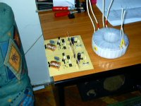
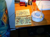
I will finish the amp in 5 day , i would post an photo with it !
P.S. I'am only a 15 year old kid ( Powerholic ) ..
Bye all
My ICQ : 349288702
I have 8 capacitor's 4700 uF , 63 V , for free from an friend .
Think 4 of them on one channel its enoth ?
Or I should put more ?
Thank's very much ! All of you !
I will finish the amp in 5 day , i would post an photo with it !
P.S. I'am only a 15 year old kid ( Powerholic ) ..
Bye all
My ICQ : 349288702
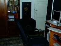
The picture with the Speaker's
This speaker's will be drive by the M250 .
In the picture is only 1 channel of 2 ..
And yes , I'AM A POWER HOLIC !!!
In a 5 x 5 meter Room i have over 300 W at a good SPL , since now i never rich 120 W because blood from my nose come out.
Thank's again Marcus and all of you that helped !
This speaker's will be drive by the M250 .
In the picture is only 1 channel of 2 ..
And yes , I'AM A POWER HOLIC !!!
In a 5 x 5 meter Room i have over 300 W at a good SPL , since now i never rich 120 W because blood from my nose come out.
Thank's again Marcus and all of you that helped !
Attachments
- Status
- This old topic is closed. If you want to reopen this topic, contact a moderator using the "Report Post" button.
- Home
- Amplifiers
- Solid State
- Another amp