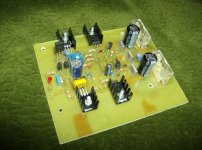
Finally i have finished one board of M250!
I have a question about idle current. After turning on the amp it was about 45ma it started to rise up. Couple of times in 5-6 minutes i had to decrease it and at the end it stopped at 95ma. Without turning pot it would be much bigger. Then i have noticed that pre drivers are getting hot. Not like burning hot. So i ask does their heat sink has to be bigger?. Here is the picture.
I have a question about idle current. After turning on the amp it was about 45ma it started to rise up. Couple of times in 5-6 minutes i had to decrease it and at the end it stopped at 95ma. Without turning pot it would be much bigger. Then i have noticed that pre drivers are getting hot. Not like burning hot. So i ask does their heat sink has to be bigger?. Here is the picture.
Attachments
geminni, Another question about pre drivers. Why are they designed to be on board? All EF (emitter follower) design has pre drivers mounted on main heatsink.
NOT TRUE!
I haven't actually built this amp myself, But quite a few others with simular output power.
And on all the amps I have made the Drivers go on the circuit board like this one.
However there are point to be made for both methods.
I also didn't design this amp.
I just did up a circuit board for it as requested by some other persons, following the origional pictures of the amp.
And the drivers were not on the heatsink in those photos.
As to your other question about the idle current.
I do not know What heatsink your using on the drivers, But with a Suitable Extruded aluminum heatsink on the PCB, it should be OK.
It also sound like your idle current is excessive for some reason.
Hope this Helps......Gary
On my previous picture the drivers are on the circuit board. After posting it i have made some changes by putting drivers on main heat sink. Well, having done something really stupid made me think to test it tomorrow. I was tired so i reversed + and - and got one burned resistor ") No transistor burned out! Maybe because i put 33ohm/17 watt resistors in both + and - rails That saved my amp
No transistor burned out! Maybe because i put 33ohm/17 watt resistors in both + and - rails That saved my amp
No transistor burned out! Maybe because i put 33ohm/17 watt resistors in both + and - rails That saved my amp The poles are staggered wrong, supply is 1hz (4R), feedback is 9.6hz, input is 3.3hz. Change feedback cap to 470µF, 4.5hz. Change input cap to 1µF, 7.2hz. Input pole must predominate, feedback pole must be between input and power supply poles. If not staggered properly amplifier will ring at infrasonic frequencies when clipped, very hard on woofers and very poor sound quality. I would also consider doubling the current in the second voltage amp, you could be running out of drive current at low impedance. Looks very nice!
some of the most forgotten but very important things
building amps.
I even had almost forgot this.

RC TIME CONSTANTS
thanks for insight djk!
wats the actual power of this amp
I have designed the PCB for the schematics which are on the page..
I have the following questions
The 8 trasistor schematic is supposed to draw 250 wats at 8 OHMs???
I plan to have 2 of the same ciruits with 16 transistors and i expect it to be a 500 watt thing at the end with both the babies on.....
please help...
FAKE MJ's???
How did you identify them ???
I mean the you were not getting desired O/P or nothing t all....
I hope mine are original.
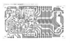
I have a PCB layout for this ...do let me knwo if any one wants it...
A very professional looking PCB
Attaching a preview of it...All you need is to get the components and Solder it....
Enjoy
How did you identify them ???
I mean the you were not getting desired O/P or nothing t all....
I hope mine are original.
I have a PCB layout for this ...do let me knwo if any one wants it...
A very professional looking PCB
Attaching a preview of it...All you need is to get the components and Solder it....
Enjoy
Attachments
Take the top off of one. If the top comes off easy, its highly likely a fake.
If you see a tiny die, or two dies, covered in white silicone, its a fake. There are some other ways to tell.
This page shows MJ15003/4 pairs, but the counterfeiters probably use the same methods on MJ15024/5's as well
http://sound.westhost.com/fake/counterfeit-p1.htm
If you see a tiny die, or two dies, covered in white silicone, its a fake. There are some other ways to tell.
This page shows MJ15003/4 pairs, but the counterfeiters probably use the same methods on MJ15024/5's as well
http://sound.westhost.com/fake/counterfeit-p1.htm
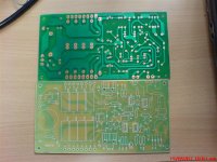
MY PCBS's are ready
Hello Guys,
Have a look at the PCB's ....dont they look Gorgeous []
I am getting sad each day, as the size of the AMP seems increasing. The second snap attached is the rectifier circuit with heat sinks for the DIODES and then the 4 capacitors take seperate space than the board.
And i have 2 MASSIVE tranformers (Non torroidal) of Six inch by Six inch by six inch. and they weigh 20KG's together.
I feel its gonna be an ugly looking Giant power Amplifier ...
Hello Guys,
Have a look at the PCB's ....dont they look Gorgeous [
]I am getting sad each day, as the size of the AMP seems increasing. The second snap attached is the rectifier circuit with heat sinks for the DIODES and then the 4 capacitors take seperate space than the board.
And i have 2 MASSIVE tranformers (Non torroidal) of Six inch by Six inch by six inch. and they weigh 20KG's together.
I feel its gonna be an ugly looking Giant power Amplifier ...
Attachments
hi Jaminator,
I wonder if you could also share the details in fabricating your PCB's.
It's long way been that I have searched for this type of fabrication.. most specially on the types of paints and some of it's processes
http://www.diyaudio.com/forums/attachment.php?s=&postid=1304862&stamp=1190175813
macweb
I wonder if you could also share the details in fabricating your PCB's.
It's long way been that I have searched for this type of fabrication.. most specially on the types of paints and some of it's processes
http://www.diyaudio.com/forums/attachment.php?s=&postid=1304862&stamp=1190175813
macweb
The baords I got it done from a small scale production guy. I gave him the layout on plastic films and he did the rest for me.
i have few more doubts guys,,,,
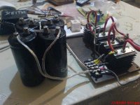
I got these 4 HUGEEEEEE 22000 mF capacitors. Am wondering if i can use only 2 instead of 4 ?
attaching few more snaps o my baby
i have few more doubts guys,,,,
I got these 4 HUGEEEEEE 22000 mF capacitors. Am wondering if i can use only 2 instead of 4 ?
attaching few more snaps o my baby
Attachments
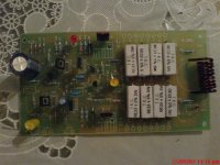

I tested last saturday and guess what
FAKE MJ15025
Replaced them with new ones but still am getting DC at the output.
I think somthing in the track work on the PCB.
Can any one help me withe the 1k preset setting on the board ?
The schematic shows only 2 ends of the preset connected and the third is not mentioned. the P1 1k preset on the schematics.
Do let me know if some one knows it.
How did you test the transistors? Electrically or mechanically?
How many volts is your DC output?
If it is something bigger then check for bad soldering, inverted transistors pins.
If DC is somewhere about 1 volts then check hfe of input transistors T1 and T2 they should be matched. I have also measured and matched R6 and R7 (27 Ohm). Mine DC is 33 mV.
When testing the amp led starts to blinks by music beat with allmost the full power. Is this normal?
- Status
- This old topic is closed. If you want to reopen this topic, contact a moderator using the "Report Post" button.
- Home
- Amplifiers
- Solid State
- Another amp