Thank you for your response wg_ski.
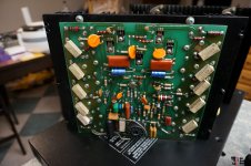
I have included pictures of the output transistors for each amp module in my post. The amp in question has Motorola transistors (BGW part numbers sj7394/sj7407) BUT, 2 NPNs must have been replaced at some point with RCA types. From what you say, given this mismatch I certainly must in fact replace the outputs, but I will not need to worry about frequency compensation as my amp was not built with Homotaxials?
I can go ahead and replace with modern matched equivalents?
As far as I can tell I could replace with 2n3773 and 2n6609 or more modern MJ21195G and MJ21196G?
J.
I can’t get the pics to load, so I haven’t been able to see. If the “mismatched” RCA’s are on the driver position, it won’t hurt anything. Drivers don’t need to be the amp as the outputs - it’s just easier to make them the same if you are replacing them. All outputs in a parallel bank need to be the same type, that’s all. That and both + and - output banks need to be all epitaxial or all hometaxial. A speed mismatch could be a problem.
If using modern types, use 21193/4, 21195/6, or 15024/15025. If you run 3773/6609 or 15003/4, you will be running them slightly beyond their Vceo rating. Not that it can’t be done, but you must pre-screen them. Manufacturers did in the old days. Original Motorola/ON 6609’s are no more. I have limited old stock, reserved for when an exact replacement is desired. I’ve also used MOSPEC 2N6609’s and had no problems with them. But I’ve only used them up to +/-60 volt rails - I have no experience pushing them to +/-84 like I have original Moto’s. They measure exactly like an MJ15004. And so do the last batch of 1990 date code Moto 6609’s (which measure a LOT different from 1980 Moto 6609’s). I suspect they are all the same part.
It is a myth that frequency compensation needs adjustment when you replace outputs with faster ones. Loop stability is generally better when the non-dominant poles are pushed higher in frequency, which is what faster outputs do. It’s going the other way (outputs too slow) when you risk loop stability problems. You can develop local instabilities if you use very fast outputs (ie, 30 MHz, with a layout suitable for 4 MHz devices) but those are almost always cured by adding (or increasing) the base stopper resistors or better supply decoupling. You can’t buy a 30 MHz TO-3 anymore anyway. At least not real one - if you get a fake you’ll get a 2N3055 die which isn’t very fast.
Hi you have great reliable and rugged amp
We have Replace all TO3 with Mj15024 and Mj15025, it works fine without issues at full output power for hours in Nightclub every Friday/Saturday 20 - 25 years ago
MJ21195G and MJ21196G - This latest TO3 BJT was not available 20 -25 years agp
have check spec onsemi website SOA is the difference I think you can use
Mj15024 and Mj15025
High SOA: 2 A, 80 V
MJ21195G and MJ21196G
High SOA: 3 A, 80 V, 1 Second
C3 you can replace with 2,2 uf 16V Non Polar
Finally: I miss the clean and powerful bass sound of the BGW amps, as well as the clear middle and highs when I went to night clubs as a teenager, so I copied the 750B / C in January 2020 and designed a circuit board.
It is the heat in Class AB which is a major disadvantage of these amps and permanently destroys the power transistors after several years of hard use, the BGW 750 B / C replica is supposed to have the latest technology added, Class TD and is then cold and efficient Similar to Class D, with an output power of 2000W
Have fun to refurbished and send pics
Last edited:
21195/6 are not significantly faster than 15024/5. It is an improved process with higher resistance to second breakdown above Vce=80 and have a little better beta linearity, but they are not really faster. The original 15024/5 are actually MORE rugged below about 50 Vce but they do make life harder for the driver transistors. These amps are in one of those gray areas where it is not clear which ones are better. Up at 100 volt rails (ie, PL700) the 2119x wins hands down.
Wg_ski: Thank you for going into detail, very useful information, I will educate myself further in this area, it is very much a learning curve for me at the moment. I am sorry the pictures do not load, I have checked and it seems they will appear If the picture links are opened in a new window, if not I will post again. The 2 anomalous RCA transistors are output stage, not driver. Yes sounds 3773/6609 I have found by ‘Multicomp’ are a long way from original Motorolas. I believe I will go for 21195/6. I gather there will be advantage in replacing the outputs as transistors made today will match better resulting in lower distortion?
Malta: Thanks for posting the comparison of specs. It is good to hear you have had experience with these amps in a club environment! When complete my 750c will be powering midrange in JBL/Altec sound system. To clarify, I can use a 2.2UF 16V for C3 even though the original part is 50uF ?
J
Malta: Thanks for posting the comparison of specs. It is good to hear you have had experience with these amps in a club environment! When complete my 750c will be powering midrange in JBL/Altec sound system. To clarify, I can use a 2.2UF 16V for C3 even though the original part is 50uF ?
J
Have fun to refurbished and send pics
I will indeed take pictures as I install new parts and clean up the amp!
IF QC in Classs TD not work. I will give up or will using Lateral P/N Mosfets
I not like BJT
Lets try soon
Either way, lateral N and P, or all N channel “hexfets”, when you start making wholesale changes like that it’s not really a modified BGW anymore. It’s a whole new design (perhaps with an LM318 input stage, but still a whole new design). Every new design has its own challenges.
Wg_ski:
Malta: Thanks for posting the comparison of specs. It is good to hear you have had experience with these amps in a club environment! When complete my 750c will be powering midrange in JBL/Altec sound system. To clarify, I can use a 2.2UF 16V for C3 even though the original part is 50uF ?
J
youtube - hear the pressure and great Sound BGW in Techno Club Installation
This club was number 1 in sound quality rating every year, more than 2 decade 1978 - 01.012001
DBX Boom box + BGW 750 C in Subbass club Installattion after repair
have fixed 1997 Sub Bass BGW 750 C with MJ 15004 / MJ15005 never fail again !!!
YouTube
YouTube
The Club Installation was
3 x BGW 750B
1 x BGW 750C for Sub Bass
3 x BGW 250C
2 x BGW 100
1. NO LIMITER in PA for best sound experience !!!
RANE MP24 later Dynacord M1
DBX Bass Boom Box
Behringer Bass Boom Box
Richard Long X Over
UREI 2x31 Band EQ from 1998 RANE 2x31 Band EQ
RG Dynamic Expander
Last edited:
Either way, lateral N and P, or all N channel “hexfets”, when you start making wholesale changes like that it’s not really a modified BGW anymore. It’s a whole new design (perhaps with an LM318 input stage, but still a whole new design). Every new design has its own challenges.
Thats true
In 1999 we got a completely destroyed BGW 750B from a friend for spare parts that nobody needed. Both PCBs were burned and could no longer be repaired.
We took the complete basic circuit of the 750B, made small changes for Mosfets as power transistors, remove VI Limiter (Mosfets are Voltage controlled) designed a new PCB and used HEXFETS as output transistors instead of the RCA / 2SJ xxx transistors. That was a fun university project in 1999 wth friends and had no commercial interests.
Then we drilled new holes in the heat sink and installed 2 new PCBs and the old broken completely destroyed BGW 750B came back to life with HEXFETS
We were surprised !! how clean and clear the sound in the middle and high was suddenly after making small changes to the circuit for HEXFETS Mosfets.
The sound was suddenly clear and clean like a Class A tube amplifier but with the power of a PA amplifier
With Hexfets as power transistors compared to the original RCA / 2Sj xxx in the BGW 750B circuit, you get clearly audible clarity and transparency in mid-range and high-frequency sound reproduction, while the bass reproduction is identical to that of the BJTs. A clearly audible difference like day and night.
However, you have to design a new PCB and make some changes. In addition to the significant improvement in sound quality, the advantages are COLD heatsink with 5 pair hexfets in IDLE compare to 40 degrees with BJTs and the 750B amplifier does not get as hot as with BJTs at full load.
Finally: 20 years later - I want try Class TD with the Basic design and Mosfets Output stage
The power supply is one of the reasons those old BGWs sound the way they do. They remain clean when driven FAR into clipping because the output impedance of the supply is very low. When an amp clips, there is no feedback and the damping factor is dominated by the supply and saturated output transistors. This is what gives older, beefy PA amps their sound. With lesser (cheaper, modern) amps that impedance is higher (many ohms, not tenths) and the bass turns to mush when clipping. If you kept the original power supply you retain these characteristics. Other improvements, or at least changes to characteristics, can be made when the amp is operating linearly and you found some that you liked. Some people prefer bipolars, others like FETs.
Finally: In todays time Class d changed everything
2012 I own BGW 8000 also very good sounding amplifier
2013 I was in Asia and came back with assembled PA Class D amplifier module, standard self-oscillating circuit with IR2110 Mosfet driver, I was surprised how good the sound was, the BGW8000 and many other competitor BJT PA amplifiers had no chance in terms of clarity and resolution.
The disadvantages with Class D are that more than 95 V DC are not really recommended, bus pumping and other problems. from 95 V DC operating voltage, a Class D amplifier should be bridged.
> 100 V DC This is where the advantages of Class TD begin, like a (BGW750B Class TD), Labgruppen FP Series
but with Class D the problems start with such high voltages.
Many Chinese PA Amplifier Manufacturer recommended Class TD for High Output power, not Class D
Last edited:
47 uf bypass for main filters
I have a BGW 750B and have really enjoyed the information here. I made the C1, C3, C11, and C12 updates with upgraded capacitors and .1 uf bypass caps. My question is about the 47uf 100v bypass caps across the main filter caps that was suggested by djk. Are these are the 210000 uf 100v oil can sized capacitors? Can anyone confirm the improved bass due to this mod. Also, I could not find a pic of this particular mod, so is it a matter of discharging the capacitor and attaching the 47 uf leads to the 210000 cap in parallel? Thank you. Herb
Add a pair of 47µF 100V power supply bypass caps across the main filter caps.
I have a BGW 750B and have really enjoyed the information here. I made the C1, C3, C11, and C12 updates with upgraded capacitors and .1 uf bypass caps. My question is about the 47uf 100v bypass caps across the main filter caps that was suggested by djk. Are these are the 210000 uf 100v oil can sized capacitors? Can anyone confirm the improved bass due to this mod. Also, I could not find a pic of this particular mod, so is it a matter of discharging the capacitor and attaching the 47 uf leads to the 210000 cap in parallel? Thank you. Herb
I have a BGW 750B and have really enjoyed the information here. I made the C1, C3, C11, and C12 updates with upgraded capacitors and .1 uf bypass caps. My question is about the 47uf 100v bypass caps across the main filter caps that was suggested by djk. Are these are the 210000 uf 100v oil can sized capacitors? Can anyone confirm the improved bass due to this mod. Also, I could not find a pic of this particular mod, so is it a matter of discharging the capacitor and attaching the 47 uf leads to the 210000 cap in parallel? Thank you. Herb
Picture upgrade 1 NF parallel to C11 and C12
> 47uf 100v NON POLAR bypass caps across the main filter caps
If you not using the amp in a club with double 15 or 18 inch Subwooder / Bass speaker each channel , you will not hear any difference, but you can add these improvements.
A lot of people give this amp a second life and using now at home for Hi-Fi, its a great amp to do it
I did it first time 20 years before with Infinity Studio Monitor and Infinity Kappa
Attachments
Silly question... maybe! just want to be sure!
I have a new fan to put in place on the noisy old one. The new one is an Ebmpapst, ACi 4410 HH, there are two tabs to connect the power supply (120Vac) cables too, I can not tell if there is a right way of connecting the wires +ve -ve, I guess it does not matter as they are no signs of polarity on the unit, and I can't find any wiring instructions anywhere, I guess the electronics in the fan will always turn the fan the correct way no matter which way round the cables are connected...?
Many thanks for any comments!
Silly question... maybe! just want to be sure!
I have a new fan to put in place on the noisy old one. The new one is an Ebmpapst, ACi 4410 HH, there are two tabs to connect the power supply (120Vac) cables too, I can not tell if there is a right way of connecting the wires +ve -ve, I guess it does not matter as they are no signs of polarity on the unit, and I can't find any wiring instructions anywhere, I guess the electronics in the fan will always turn the fan the correct way no matter which way round the cables are connected...?
Many thanks for any comments!
In the UK we have about 230 V, why do you ouse 120V AC Fan ?
AC no need polarity, you can connect with main Switch ON/OF Switch
Do you using the amp at home ? then Fan is very noisy
If you have electronic skills, you can upgrade to 12V PWM temperatur controlled FAN Speed / FAN off < 40 degress heatsink.
I did make this changes with my 750B, because its running at home to drive large HI-FI speaker and subwoofer.
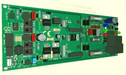
For my DSP Board I need for 8 Channel 8 x 750B output Module, its not available to buy
In this case I have copy 750B output Module with small improvements
I have design PCB, 200mm x 80mm, all in one (TRIAC Crowbar DC Protect - Clip Limiter - DISPLAY - Relais Turn ON Delay / OFF )
scalable output power from 50 to 2000W, most of the semiconductor are SMD
Big output power have more output Devices and PCB is larger
Last edited:
If somebody like it to build contact me
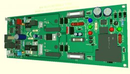
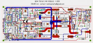
BGW 750 B/C MK1 rebuild 200 x 80 mm - Switching Power Mosfet Output Devices
The Output stage using UNIFET Mosfets FDA69N25 v/s TO3 BJTs in Original design
2 pair UNIFET Mosfets FDA69N25 250V - 69A - 480W
rugged, cheap, reliable
Price: EUR 3,29 pcs.
and can do same Job, with huge improvement clarity in Sound (Mid and Highs)
v/s 6 pair RCA/2SJ MJ15024/25 TO3 BJT in 750 B/C
Price: EUR 6,33 pcs.
I want try to add soon Class TD, development help is welcome
also I share my Gerber PCB Files for all who are interested.
In todays time to order PCB from Factory (pcbway.com or jlcpcb.com)
cost 5 USD from China + shipping cost
Attachments
Well that was a total waste time, the new one is quite a bit louder than the ancient rattly one... the new one wines! old one just created wind noise and rattles, new one wines so much you can't even hear the wind noise... why!!? new technology should be able to make fans that don't wine! - it says in the spec it is specially designed to generate less wind noise!
Ahhh!
Malta - cheers for the info. +ve -ve does not matter. Unfortunately my electronic skills are not up to anything other than replacing original with same replacement parts at the mo. Although the fan situation is not good, I may need to learn!
It does seem to be going a fair rate of knots, so maybe I shall see if I can check the temp checkers, if they think its hot for some reason then maybe I should change them - maybe I should squirt the old fan with WD40 see what happens, the original fan would be nice if it is running fast at the mo.
Yes it is used at home... well not yet.. its too noisy.
Cheers
")
Ahhh!
Malta - cheers for the info. +ve -ve does not matter. Unfortunately my electronic skills are not up to anything other than replacing original with same replacement parts at the mo. Although the fan situation is not good, I may need to learn!
It does seem to be going a fair rate of knots, so maybe I shall see if I can check the temp checkers, if they think its hot for some reason then maybe I should change them - maybe I should squirt the old fan with WD40 see what happens, the original fan would be nice if it is running fast at the mo.
Yes it is used at home... well not yet.. its too noisy.
Cheers
Okay, spec said the fan should run at 42dB
Just measured 1m away at 58dB and up close at 70dB
So asking supplier for suggestions...
I don't know much about dB, if the room had background noise of around 37db, should the fan add 5db making a max room sound of 42dB or does the 42(fan) get added to the 37(room)? Am I making things complicated!?
Cheers
Well that was a total waste time, the new one is quite a bit louder than the ancient rattly one...- it says in the spec it is specially designed to generate less wind noise!
Ahhh!
It does seem to be going a fair rate of knots, so maybe I shall see if I can check the temp checkers, if they think its hot for some reason
Yes it is used at home... well not yet.. its too noisy.
Cheers
Hi
1. Dont believe spec, you need temeperatur controlled 12V Fan
2. BE CAREFUL,...BJT output stage, without cooling,
running very warm also in IDLE
20 years ago
have replace 1 Channel with Switching Power Mosfet Output stage
other Channel was original BGW 750B Module
The Reason, Mosfet Channel with 5 pair IRFP240 was cold in IDLE
and Original BJT Channel about 40 - 50 degrees in IDLE
after 1 hour
Thats the Reason why Ecler using Swiching Power Mosfets in PA Amplifier,
the amp is not hot like with BJts
Idle Current for Swiching Power Mosfet is about 40ma for BJT x 10
Last edited:
- Home
- Amplifiers
- Solid State
- BGW 750B output modules