Okay, I have started to disassemble the amp to give it a good clean and to see if I can find anything obvious on the chassis circuit as to why only one side works, and not the other. The Gain control pots have no wires to the centre pin, wiper I guess, its difficult to see at the moment but it looks like, the middle tab was used but the wiper wire has been moved to either pin 1 or 2.
I am trying to understand the circuit diagram, I wonder if anyone may help explain the attached diagram to me as I don't get the horse shoe, or crap pincer part of the diagram. Almost like a clamp around the wire coming out of tab 2, the wire from the clamp then goes around, joining to tab 3 and then around to the input side with the clap like symbol near to tab 1. Is the horse shoe or clamp symbol an actual joint?
My thoughts are to minimise connections and lengths of wire, therefore bypass the pots, but I am a little unsure how. Just trying to understand the diagram to give me a clue as to how.
Many thanks
DC
Attachments
I'm trying to get it working.. hence going through the chassis wiring, trying to learn/understand whats going on, where, and thankfully it looks pretty simple! as I can follow wires around which is much easier for me than circuit boards ;-)
Thank you for the shielded explanation of the crab claws! makes more sense now")
If I were to dispose of the shielded wires going to the pots, and connect directly from the input jacks to the 11 pin module plugs, I am thinking I would need a 22KOhm resistor connecting between the hot and earth of the single ended input jack. Am I working things out along the right lines?
I don't need the volume pots as the pre or crossover will control the levels, I am just trying to simplify things as much as possible and hopefully the fault may just vanish with simplifying things, and a bit of re-soldering here and there... the pots measure differently to each other.. so I guess something is a miss in this area...
Thank you for the shielded explanation of the crab claws! makes more sense now
If I were to dispose of the shielded wires going to the pots, and connect directly from the input jacks to the 11 pin module plugs, I am thinking I would need a 22KOhm resistor connecting between the hot and earth of the single ended input jack. Am I working things out along the right lines?
I don't need the volume pots as the pre or crossover will control the levels, I am just trying to simplify things as much as possible and hopefully the fault may just vanish with simplifying things, and a bit of re-soldering here and there... the pots measure differently to each other.. so I guess something is a miss in this area...
Yea I know, I may be a little slow
learning!
Just measured between hot and earth on the inputs:
(nothing connected)
left input 10KOhms gives sound through speaker when all connected and switched on.
right input 20KOhms does not give sound
Parts list says 22KOhm pots
measured signal input pin to earth at the 11 pin connector too, agrees with above, 10 and 20.
I am worried if I correct the 10K Ohm to 22 it will stop working that side too...
Any thoughts?
Hi Deaf Cat,
You could use a 10 K pot. It would not cause one channel to stop working.
I would leave the volume controls in if I were you. They allow you to mute the amplifier if you need to change input cables. Always turn the amp off if you are touching the output cables. If you need to replace them, anything around 20K would work, so you could use a 25 K pot without any drawbacks. You don't need exactly 22 K pots.
There is an easy way to check the other channel you know. Just remove the left module, then connect the right module in it's place and then install the left module in the right hand spot. The wiring is identical. The only thing I can see that might worry you is the wiring to the temperature limit switches. One kills the AC power, the other disconnects the speaker output. It is possible you have a faulty temperature limit switch. Anyway, do that for a quick check.
-Chris
Chris, cheers for the tip on the pots, shame, I was thinking that just, maybe, correcting those would get the thing working, but I could not see how to be honest, can but hope ;-)
Yes I have already switched amp modules back and forth, either one works in the left bay, neither work in the right bay. Hence checking through the chassis wiring...
Think I may check out the bridging switch next, work out what it is supposed to connect to what and check it is switching correctly as that is on the RHS bay/module.
Cheers
Hi Hi Deaf Cat,
phase is suggesting the same thing I was. You can test these switches with a good ohmmeter. They should both read short. Make certain there is no power applied! It sometimes helps to tap the switches while making the test.
So you know both modules are good then, excellent. The bridging switch is a good place to check too. Bridging amplifiers isn't a great idea. If there is one control I'm at peace with you eliminating - it's that one.
-Chris
Ok, I see that the 340/350 parts are still available, it was the mje 720 that was hard to find before.
I just found the post from Anatech (thanks!)where there had been suggested substitutes...
Need Assistance: To220 replacement for MJE720 or 2N2219a
MJE 180 is replacement
BGW use MJE 180 in latest 750 Model ( 750 F / G and Model GTB )
The MJE720 was used as the BIAS TRACKING. It is a TO126 not a TO220 and the house # 2450. The house part was selected for 5Vce @ 10ma with BETA >100.
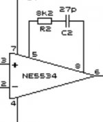
The NE5532 is a UNITY GAIN opamp and needs no comp for stability. The NE5534 needs comp of the gain must be > 3x
Duke
Hello Duke
BGW no have comp for NE5534 in Model 150 from 1981
Front End circuit is same, like Model 100 /250 C/D/E / 750 A/B/C
but BGW replace LM318H with NE5534 without comp at PIN 5 and 8
what do you think about value for comp NE5534 at PIN 5 and 8
if replace LM318H with NE5534a in Model 750 B/C
8k2 and 27pf in series same like in PIC for BGW 750 B/C ?
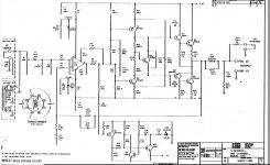
1. Schematic from 1976
BGW Model 100 with LM 318 have comp fot stability
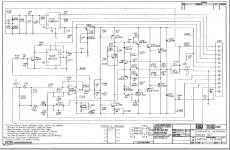
2. 1. Schematic from 1981
BGW Model 150, NE534 no have comp for stability
.....BGW have replace LM 318 with NE5534
Finally: when you leave BGW (what year) ?
regards
Attachments
Hi NMOS
The NE5534 does not need any comp if the gain is >3x (The bandwidth is much lower). The LM318 has 15Mhz bandwidth and it needs comp for stability.
I removed the LM318/NE5534 from the front end and used discreet semi in many models as the turn ON and OFF thumps are well controlled vs OPAMPS.
They also had no output relays so the QUIET MUTE was needed.
I left BGW in 1985/86?
BGW no have comp for NE5534 in Model 150 from 1981
Front End circuit is same, like Model 100 /250 C/D/E / 750 A/B/C
but BGW replace LM318H with NE5534 without comp at PIN 5 and 8
what do you think about value for comp NE5534 at PIN 5 and 8
if replace LM318H with NE5534a in Model 750 B/C
8k2 and 27pf in series same like in PIC for BGW 750 B/C ?
The NE5534 does not need any comp if the gain is >3x (The bandwidth is much lower). The LM318 has 15Mhz bandwidth and it needs comp for stability.
I removed the LM318/NE5534 from the front end and used discreet semi in many models as the turn ON and OFF thumps are well controlled vs OPAMPS.
They also had no output relays so the QUIET MUTE was needed.
I left BGW in 1985/86?
Hi NMOS
The NE5534 does not need any comp if the gain is >3x (The bandwidth is much lower). The LM318 has 15Mhz bandwidth and it needs comp for stability.
I removed the LM318/NE5534 from the front end and used discreet semi in many models as the turn ON and OFF thumps are well controlled vs OPAMPS.
They also had no output relays so the QUIET MUTE was needed.
I left BGW in 1985/86?
Thank you for Information this helps me
I want Redesign
750B MK2 Class H step driver Rail +/- 100 V
real 1000W RMS @ 4 Ohm (not fake PA power)
to driving subs and bass boxes
LM3915 IC DOT BAR DISPLAY Driver is obsolete
with todays Bipolar semis like in 750G schematic no problem
or N Channel Mosfets Output Stage
I scare big power with Bipolar semis
Last edited:
XLR PREAMP for 750B front end
Hi Duke
please have a look at the 750B Fromt end circuit
have add XLR preamp with volume control
Can I remove LM318 from front end and drive from NE5532 output
or its not good idea to change something in the circuit ?
Can you remember what was the reason to change in Model 150 to NE5534 compare to previous Model 100 with LM318
is 5534 improvement in Sound compare to LM318 ?
From datasheet LM 318 have much better performance....
Attachments
The 553x are lower noise op amps. The reason the 318 is “faster” is because it is decompensated. When compensated for unity gain there is no advantage. The 5532 is plenty fast enough in the application. The 318 was a huge improvement over the 301 and 307, but technology has moved on (back in the 80’s even). You could experiment with modern op amps for even more improvement, but be careful of fragile input stages. In this type of amplifier it is imperative to use a diode protected input stage or the op amp will die from just one turn-on transient.
This type of amplifier works quite well with rail switches if you follow a few simple precautions. Run the VAS at full supply. Use the full complementary output. Earlier versions with the RCA 2N6259 outputs will not work with rail switches - even if you switch to a faster output like the 15024. It oscillates audibly every time the rail switches and it cannot be fixed. Stick in PNPs in the bottom half and the problem magically goes away.
The 3915’s are disappearing rapidly. Last time I looked Digikey had about 2000 left. A couple of the surplus dealers areound here still have them - but probably not for long. I did my lifetime buy a couple months ago. Along with other things that are soon to go away in DIP packages.
This type of amplifier works quite well with rail switches if you follow a few simple precautions. Run the VAS at full supply. Use the full complementary output. Earlier versions with the RCA 2N6259 outputs will not work with rail switches - even if you switch to a faster output like the 15024. It oscillates audibly every time the rail switches and it cannot be fixed. Stick in PNPs in the bottom half and the problem magically goes away.
Thanks for Info about LM318 / NE553xxx
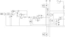
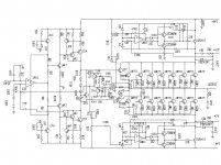
Please look schematic PA Class H Bipolar N channel output stage 2n3773
I find schematic about 10 years in this forum
Front End similar like BGW750 A/B/C
Do you think 2n773 in this schematic will oscillates audibly every time the rail switches same your Earlier versions with the RCA 2N6259 outputs ?
No way Class H rail switches with quasi complmentary output stage ?
Attachments
Last edited by a moderator:
- Home
- Amplifiers
- Solid State
- BGW 750B output modules