measuring time delay of Vbe multiplier
Who has a three or four channel logging system?
Can I suggest an experiment?
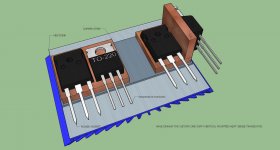
mount three identical transistors, preferably matched for Vbe @ a fixed current, at three different locations on the output stage.
1.) on the heatsink between the output pair.
2.) on the back of one To247/264 device.
3.) on the collector leg of one To247/264 device.
Feed a constant current into each of the monitoring transistors and measure/log the Vbe of each.
Now feed a gated current into the output pair to raise the device temperatures. Gated on for 60Seconds @ about 80% of SOA capability.
watch the Vbe of each of the transistors and follow what happens when gated back off. A fourth logging channel could be used to see the time delay in both temperature rising as well as temperature falling.
This could be repeated for various on/off duty cycles, once the time constants have been estimated.
Who has a three or four channel logging system?
Can I suggest an experiment?
mount three identical transistors, preferably matched for Vbe @ a fixed current, at three different locations on the output stage.
1.) on the heatsink between the output pair.
2.) on the back of one To247/264 device.
3.) on the collector leg of one To247/264 device.
Feed a constant current into each of the monitoring transistors and measure/log the Vbe of each.
Now feed a gated current into the output pair to raise the device temperatures. Gated on for 60Seconds @ about 80% of SOA capability.
watch the Vbe of each of the transistors and follow what happens when gated back off. A fourth logging channel could be used to see the time delay in both temperature rising as well as temperature falling.
This could be repeated for various on/off duty cycles, once the time constants have been estimated.
Yesterday afternoon, exhausted after a long day of Christmas carols, I poured a martini and got out Jim Williams "Analog Circuit Design", put a log on the fire and some Russian Christmas Music on the system. I read over the chapter "Good Engineering and Fast Vertical Amplifiers" by John Addis -- detailing the development of the vertical amplifiers for the Tektronix 7904 and 7104 scopes (I think it was the 7A29) -- the thermals were what they were most concerned with.
Might find this interesting:
http://www.ieee.org/portal/cms_docs_societies/sscs/PrintEditions/200710.pdf
Might find this interesting:
http://www.ieee.org/portal/cms_docs_societies/sscs/PrintEditions/200710.pdf
This fact is something I have already commented altough nobody seemed to trust me. I also did the same experiment in the past and got the same frustrating results as you
The worst place to mount a Vbe multiplier is over the plastic case of a power device. This plastic resin usually has very high thermal resistance and just does not follow the die temperature at all, actually it's allways sustantially cooler than the heatsink and much cooler than the die itself. The temperature of the plastic surface is mostly dependent on ambient temperature only
This idea maybe?, yes tread is old but the problem is'nt. Using a copper bar, above the insolation layer copper do have very good thermal properties and transport heat very fast.
I have now us the plastic case for mounting the sense transistor and as eva says, it do not work wel except for small demands, low power amps, I get a drift also, it stays first for a 30 minutes stable and then go drift, first up then down, if i have 500 mA setup, it go drift after 30 minutes to 600 mA then to 350 mA back to 500 stays there and repeat.
I need als the inverting buffer to gert nuch less heat sensitive, the inverting I do need because I have regulation the positive way.
regards
Attachments
Last edited:
If you go to Bonsai's Hifisonix website, you'll see just how good his results were with a tiny SMD transistor right close to the collector lead where there is very little thermal lag that occurs through the heatsink and insulation material. Speed is of the essence here, even if there is a net temperature differential between die and sensor.
The full E-Amplifier article is on his site with details and discussion on the thermal comp. at 7.10 here: Ovation e-Amp: A 180 Watt Class AB VFA Featuring Ultra Low Distortion.
The full E-Amplifier article is on his site with details and discussion on the thermal comp. at 7.10 here: Ovation e-Amp: A 180 Watt Class AB VFA Featuring Ultra Low Distortion.
If you go to Bonsai's Hifisonix website, you'll see just how good his results were with a tiny SMD transistor right close to the collector lead where there is very little thermal lag that occurs through the heatsink and insulation material. Speed is of the essence here, even if there is a net temperature differential between die and sensor.
The full E-Amplifier article is on his site with details and discussion on the thermal comp. at 7.10 here: Ovation e-Amp: A 180 Watt Class AB VFA Featuring Ultra Low Distortion.
You are quite right, special with a very low on resistance mosfet I need speed.
I have now testing the CFP setup with a sense transistor, I get now a stable readout, but it starts on low idle like 400 mA and go up to there but when on 500 ma it stays there within plus minus 50 ma, do I cool the whole thing down it go up to 600 mA who is because I do use air and cool also resistors, CFP etc...
I did read a time ago samething about that, I did that time a experiment with temp resistors, but also what I did drawn, with copper bars between the power mosfet and the insolater, then we get very fast respons also.
I have mosfets, people say that I have to use mosfet sensor also, then I need a mosfet with also very low on resistance also.
Dp remember, mine multilier has a idle current of 40 mA itselfs, warm up the CFP and as such it does add some extra disturbance, I have connect the two transistors thermally of the CFP not it keeps quite stable.
regards and thanks for links.
Attachments
Last edited:
After a cold start of amp, it is 400 mA rise quickly to 800 mA and drops again to 400 mA and slowly stabilizing on 510 mA and stays there within plus and minus 50 mA.
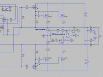
Do someone know how to use a fet as a temperature sensor, gate to drain ? or a separate gate voltage. see schematic above.
The idea with a smd transistor is nice however I have a mosfet output stage, it is some different in thermal behavior, and I have a different regulation deeded, like in a normal vbe multiplier the impedance gets lower and as such less idle current, in mine case I need to have a higher impedance to get the current lower because it is a circlotron where I use the multiplier from ground ref resistors to ground, having there 8 volts, and a current through the multiplier of 45 mA what is higher as a normal multiplier.
Hi kees52,
It would seem to me that what you really need is an indication of temperature that varies without any second or third order effects. Not trying to seem flip, but JFets make a great diode. Then use them the same way you would a diode or BJT. Expensive diode though.
The characteristics of a JFet don't match mosfet types used for output transistors. You might be further ahead just doing it the way others have done before. That's a lot better than the types I see based on a semi-fixed resistor.
-Chris
Hi kees52,
It would seem to me that what you really need is an indication of temperature that varies without any second or third order effects. Not trying to seem flip, but JFets make a great diode. Then use them the same way you would a diode or BJT. Expensive diode though.
The characteristics of a JFet don't match mosfet types used for output transistors. You might be further ahead just doing it the way others have done before. That's a lot better than the types I see based on a semi-fixed resistor.
-Chris
Hi Anatech
Thanks for the respons, I be aware of the way others did but for me I have some quite different commands, first, a multipier between two basis of transistor is used a lot, these do get lower impedance when get warm and as such lowering the idle current, and the idle current through the multipier is just 4 or 8 mA.
However for me I need a rising impedance when get warm, and I have 45 mA idle through the multiplier buffer transitors and have some dissipation what does have influence on stability, that is why I did connect thermally the CFP stage.
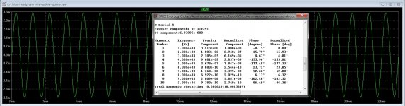
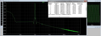
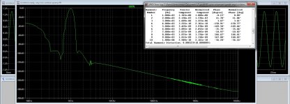
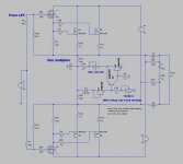
As I now see it is a to high thermal resistance between the sensing transistor and the mosfets also, using the plastic housing doe work but not when it is a high power amp, but I get with this multipier 0.000421 procent distortion on 5 amp output and a distortion on 1 amp output as in pictures on simulation.. this is with laterals however, but vertical do also nice, see pic 2 with the used multiplier..
Maybe the use of a ntc for the mosfet idle protection? these do fine when used properly.
But I need to place this on mine circlotron thread afcourse.
regards
Attachments
Hi kees52,
Okay, then why not use whatever bias compensation that sort of works. Mount a few devices to sense temperature on the heat sink as well. Experiment with how they respond to temperature changes to see if it would be useful.
Doing this merely allows you to experiment more easily and to change connections while the amplifier remains powered up. I wish I could suggest something more useful to you, but this will save time for you.
-Chris
Hi kees52,
Okay, then why not use whatever bias compensation that sort of works. Mount a few devices to sense temperature on the heat sink as well. Experiment with how they respond to temperature changes to see if it would be useful.
Doing this merely allows you to experiment more easily and to change connections while the amplifier remains powered up. I wish I could suggest something more useful to you, but this will save time for you.
-Chris
I have now some other sort of test ready, and if I can not test and have copy things then I have less pleasure.
using multiply parts makes things more complicated, I think a sensetransistor/ntc combination as mention here can be a nice solution.
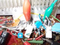
I have now ready a smd transitor whop go onto the drain lead, and adjust, I am curious what it brings.
regards
Hi kees52,
The bunch - o - parts were there for you to experiment with each one. I did not think you would try to use all in one circuit. This would allow you to evaluate each type of circuit without having to shut things down. Once you found something promising, you could rig that up and make it work.
-Chris
The bunch - o - parts were there for you to experiment with each one. I did not think you would try to use all in one circuit. This would allow you to evaluate each type of circuit without having to shut things down. Once you found something promising, you could rig that up and make it work.
-Chris
Hi kees52, The bunch - o - parts were there for you to experiment with each one. I did not think you would try to use all in one circuit. This would allow you to evaluate each type of circuit without having to shut things down. Once you found something promising, you could rig that up and make it work.
Oke I has already such idea you did mean it this way.
Yes I have already done some different things and I have some kind of succes, but asking you guys who have also experience do never harm.
I go tomorrow glue a very small bc817 to one of the power mosfets drain pins and watch the wonders who happen.
Thermal connections has quite big challences.
I have to find me a wife, after 14 years of freedom.
regards
Last edited:
I have seen this link
http://hifisonix.com/wordpress/wp-c...on-for-Audio-Amplifier-EF-Triples-V1.0231.pdf
Nice to read.
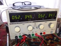
I have now a setup who do start on 600 mA (I did have 500mA as a goal) drops very fast to 420 mA and rise again to 520 mA and stays there, after a while it drops to 490 mA and a heatsink temperature of 75 degrees, quite hot, no very hot, it drops to 390 mA if I let it, then ur rise again to 490 mA and pendles there, with a good heatsink (I have one who needs to get hot for test) then it is quite stable.
Only what I do sometimes see are drops, it drops then 40 mA in a second, and then rise slowly, maybe here is some instable action.
regards
http://hifisonix.com/wordpress/wp-c...on-for-Audio-Amplifier-EF-Triples-V1.0231.pdf
Nice to read.
I have now a setup who do start on 600 mA (I did have 500mA as a goal) drops very fast to 420 mA and rise again to 520 mA and stays there, after a while it drops to 490 mA and a heatsink temperature of 75 degrees, quite hot, no very hot, it drops to 390 mA if I let it, then ur rise again to 490 mA and pendles there, with a good heatsink (I have one who needs to get hot for test) then it is quite stable.
Only what I do sometimes see are drops, it drops then 40 mA in a second, and then rise slowly, maybe here is some instable action.
regards
Hi,
Thanks, I'll have a read. You never know when you might pick up something truly useful.
-Chris
Your welcome.
Looks like it is a succes.
after switch on, around 600 mA after 5 a 10 seconds it stabilize, then it keeps Idle current between 500 and 550mA with a temperature of the heatsink between 25 (ambient) until 85 degrees, then drops to +- 450 mA if 90 degrees approaching.
I have used a smd BC817 glued on the Drain lead. It respons very well, starting cold on 600 mA and drops in 5 seconds to 500 and pendels there.
What I do see is sometimes little drops like 20 mA in fractie of seconds and back, maybe some unstability but maybe it is normal because it is just 20 mA.
regards
Attachments
Last edited:

Member
Joined 2009
Paid Member
Hi Gareth,
The one place where you don't really want excess resistance is in the emitter circuit of a common emitter output stage. The other factor that is effective is the heat sink. If it's too small, you will have bias stability troubles.
Hi kees52,
I can see the smt glued to the collector lead as a very effective sense point. The thermal track mounted the sensing diode on the collector heat spreader internally. Sticking an smt to the collector lead is about as close as you're going to get outside the package.
Of course, that makes service a PITA! On the replacement part you'll have to glue another smt, without markings to know what it was. Hopefully it is used as a forward biased diode so that any one will do. Then, connecting the leads could be tense. Use kynar wire or single strands from wire? Either one is a total joy to work with. I can see the possibility of someone ripping the output out without seeing the smt, then you have the classic amp that no one can repair. Not unless you leave a note in the chassis.
-Chris
- Status
- This old topic is closed. If you want to reopen this topic, contact a moderator using the "Report Post" button.
- Home
- Amplifiers
- Solid State
- Vbe Thermal Coupling Issue