I made modifications.
Simulates very well, but this do not guarantee nothing related the sonic qualities.
Can tell me if will work or not...and worked very reasonable.
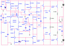
Easy can produce 150 RMS watts to 8 ohms.... to reach something alike 250 or 300 hundred watts can be reached if supply can hold the power needed.... 600 Watts transformer may work with 4 ohms speakers.
If you want to connect to hard loads, as 1.5 or 2.0 ohms, put 4 pairs of 250 watts transistors.
3dB loss is around 5 hertz and 105 kilohertz.
The MPS transistor can be replaced with some 100 Megahertz that can hold more than 100 volts peak to peak swing.
Square wave shape remember a Vulcano when full power is reproducing frequencies higher than 60 Kilohertz.
Low frequency shows sligth overshot
Sinusoidal turns triangle around 120 Kilohertz
Square wave turns ugly around 108 Kilohertz
I am thinking in assemble that complicated thing...do you think this will sound good?
Could you find errors?
Have something to include or supress?
Please, having something to say.... go ahead.
regards,
Carlos
Simulates very well, but this do not guarantee nothing related the sonic qualities.
Can tell me if will work or not...and worked very reasonable.
Easy can produce 150 RMS watts to 8 ohms.... to reach something alike 250 or 300 hundred watts can be reached if supply can hold the power needed.... 600 Watts transformer may work with 4 ohms speakers.
If you want to connect to hard loads, as 1.5 or 2.0 ohms, put 4 pairs of 250 watts transistors.
3dB loss is around 5 hertz and 105 kilohertz.
The MPS transistor can be replaced with some 100 Megahertz that can hold more than 100 volts peak to peak swing.
Square wave shape remember a Vulcano when full power is reproducing frequencies higher than 60 Kilohertz.
Low frequency shows sligth overshot
Sinusoidal turns triangle around 120 Kilohertz
Square wave turns ugly around 108 Kilohertz
I am thinking in assemble that complicated thing...do you think this will sound good?
Could you find errors?
Have something to include or supress?
Please, having something to say.... go ahead.
regards,
Carlos
Attachments
Hi Carlos !
Looks fine, except maybe the "unbalanced" input. The inputside of
diffamp has 11kohms, the feedbackside has 22kohms. This can
give some DC-offset.
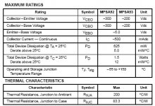
The bd139/140 has 80volts ratings, but might see more than
100volts. Why the mpsa92 ? This transistor should not see more than 55volts.
You might consider a 1k basestopper on the lower bd139 in the vas
for safetyreasons.
Ok, sofar looks okay, i see no further problems.
What transistors are you using for outputstage ?
Mike
Looks fine, except maybe the "unbalanced" input. The inputside of
diffamp has 11kohms, the feedbackside has 22kohms. This can
give some DC-offset.
The bd139/140 has 80volts ratings, but might see more than
100volts. Why the mpsa92 ? This transistor should not see more than 55volts.
You might consider a 1k basestopper on the lower bd139 in the vas
for safetyreasons.
Ok, sofar looks okay, i see no further problems.
What transistors are you using for outputstage ?
Mike
Thank you MikeB and Jan Dupont, i did not constructed yet
I am just thinking about to construct.
We bougth a new furniture to the television and audio room, and some pretty wood panels and some perfurated chromium plated parts were not used to put Cds inside.
This way, having the pretty enclosure, and very big, i was thinking in construct something stronger than the average power i normally have here "Watt vírus powerholic" are attacking me.
Yes Jan i know very well you like the simetrical, double simetrical inputs used in your Linnx and others you have on your manufacturer line.
I am trying some Digital and feel that cannot betray my old tradition of AB and C.
So, i may do this one...not sure. To be more decided i put it here to have some evaluation from our forum people.
I take note your modifications my dear friend from Good luck place (guterloh is impossible to me to pronunciate.... happy not to have bonds in my tongue...because if bonds inside i had...they were broken trying to pronouciate your town name Mike)
Thank you the family picture Mike....i was happy to see your best friend, his wife and your mother...and you are really big!
Well, is good to see that spirit of cooperation, this way i love to post schematics, i think interesting different oppinions and ideas...many ideas i use to test here to see if i like the audio results.
thank you.
Carlos
A: My faith in the predictive power of simulation is limited but I see nothing obviously amiss. Ultimately one has to build it in order to know.
B: There are two things I would do differently if it were my project, but that does not mean there is anything "wrong" as it is. Just my own preferences. Just so you know, they are:
B1- For 150W I would use three rather than two pairs bor better
heat transfer and less distortion penaty at low loads.
B2- Instead of connecting the driver emmitters to the output via a
pair of 33-ohm resistors, I would connect these emmitters only to
each other via a singple 150-220 ohm resistor by passed by an
~1uF cap. This improves crossover distortion by forcing one side
off when the other turns on.
Would anyone notice the difference when listening? Who knows? Probably not.
2SA870 and 2SC2240 is used in good Yamaha amplifiers.
To the output MikeB, i have two pair of those rectangular 250 watts Sanken Devices...not the last models, a little bit older...2SA1215 and 2SC2922.... they are always the same, as i am using them to all the amplifiers i make.... to driver i think i will borrow some Aksa drivers transistors...just for testing purposes, as it will return to Aksa again...guaranteed.
Yes!...those BD139 sometimes hold a little bit more voltage...also the BC556, those values of maximum voltage are not so precise.
A long time ago we could see some "load charge lines graphics" to see where the transistor are more linear, and decide the best current to your working voltage...but i did not perceive those graphics anymore....i will see some Ic/Ib to try do deduce the best point, and to adequated better thetransistors choices...i am just using some reference schematics, from products, published by our forum friend Matt www.schematicsforfree.com , those schematics i use to have one idea if the transistor is adequated or not..if works well, in some Yamaha, using the same voltage and current i will intend to use, i suppose i can conclude that will work fine in my amplifier too... am i rigth?
But the question is...is this kind of schematic, with all those CCS and mirrors, good sounding circuits?
I made some last year, and i dislike those more complicated circuits, maybe some matter of coincidence...the more complicated resulted in worst sound...maybe because all tollerances out working together (and bad!) so, i was running from them a long time.
Now going again to complicated designs.... not sure if will sound good...that's i would be happy to hear someone saying to me:
" I assemble one circuit with the same CCS, using the same red LED and those mirrors and same thopology and sounds this or that way"
That's i am searching, that kind of information....can be subjective feelings.... alike:
"Hummm, those mirrored normally sounds so so so despite having excelent slew rate"
regards,
Carlos
a true beast
it is hard for me to say if it is sophisticated or over-complicated (with so many stages and huge open loop gain)
TRY IT
what's the purpose of 6,8k at colector of bc546 at current souce?
this amp looks more like (old-stylish??) commertial amp then a diy project I feel.....
regards
it is hard for me to say if it is sophisticated or over-complicated (with so many stages and huge open loop gain)
TRY IT
what's the purpose of 6,8k at colector of bc546 at current souce?
this amp looks more like (old-stylish??) commertial amp then a diy project I feel.....
regards
Re: Carlos
My point was, that a mpsa92 is a bit overkill here, it's a highvoltagebjt,
not a real smallsignal one. So a bc556 would do a better job.
And i would always use original onsemi-parts, i once had non-onsemi
mje15030/31, they gave nice firecrackers...
Maybe i bug you, but the bc546b/556b are quite good transistors,
and their +/-65volts are enough here...
I see no real reason to use the sc2240, which has about ten times
the price. (At least here in germany, the bc546 costs 4cents, the
sc2240 > 40cents)
In sims, the bc546 often outperforms the sc2240.
Maybe a mpsa18 would be perfect here, as diffamp is cascoded,
their low max-vce is no problem. (or mps6521 ?)
Mike
ACD said:Which make of MPSA92 do you use ????????
Fairchild / Onsemi's MPSA92 are rated 300V, and can handle it!
Trust me as the MPSA's are one of my favorite amp transistors")
My point was, that a mpsa92 is a bit overkill here, it's a highvoltagebjt,
not a real smallsignal one. So a bc556 would do a better job.
And i would always use original onsemi-parts, i once had non-onsemi
mje15030/31, they gave nice firecrackers...
ACD said:I don't think I have to tell you my opinion, as you well know my view on non sym. amps
And maybe you should use 2SA970 / 2SC2240 in the input
Maybe i bug you, but the bc546b/556b are quite good transistors,
and their +/-65volts are enough here...
I see no real reason to use the sc2240, which has about ten times
the price. (At least here in germany, the bc546 costs 4cents, the
sc2240 > 40cents)
In sims, the bc546 often outperforms the sc2240.
Maybe a mpsa18 would be perfect here, as diffamp is cascoded,
their low max-vce is no problem. (or mps6521 ?)
Mike
hi guys,
actually Mike has my words those BC's are worth trying for.
I've been using these devices with my new completed design, but also in the thread by this time open for comments and suggestions.
This beast has been around for maybe two weeks and been shaking the house every corner.
This design is a quasi-complementary output stage topology pretty overlooked design. Rather the design was born becuase I could hardly
find MJL21196's friend, MJL21195, here at home. No stores sell them.
Jan: soon I'll be able to complete the LYNX, I hope TI will be kind enough to donate some samples of OPA627's. (macweb)
Hienrich
Attachments
I like the way you think Mike, and accept others that say some transistor ....
I like you ideas MikeB, they have my support too, but i also accept that there are some very special transistors that have some good hi frequency response too. And if someday Jan induces me to check those differences, as i know he is good, i will check his words in field testing...Other guy is Spencer from North Lands....when he open his mouth, you can hear the echo of Knowledge invading our years.
Aksa amplifiers made me check that.... without good drivers sound lost quality, and i am always trying to introduce BD139, because they are good, because i like them...this is a problem to development of my own knowledge.... believing that, i will not try others...and who can guaranteed to me that another cannot produce better sound...i use BD139, because it is cheap, well constructed, small, good gain, and can oscilate in radio frequencies, as i am using as drivers to send 1 watt to Citizen Band output devices, and sometimes as pre-drivers in more powerfull Single Side Band transmitters (30 Mhz top frequency HF bands).
But there are people that say MJ340/350 (or MJE340/350) are much better.... and they guarantee that those really are... but this inform you can have mailing directly...people have not courage (the majority that thinks this way) to post that on forum.
I do not know what is really better .... i suppose they have current, voltage limits,gain, frequency response, appearance and price..... and the human preferences, having thousands that can fit the same circuit place, without any trouble.
But there are people that say some transistor sounds this way or that way....i could not perceive those details, can be my fault as a not perfect listener..only high frequency differences i could hear...maybe i do not have a good ears!....of course i have to take that into my account, as i have 54 years old, and 45 years assembling amplifiers, now going to make number 4382 amplifier, maybe this one i am showing, the amps lab modified to my way...just that...i did not calculate nothing, only use my experience to modified here or there...very feel modifications i guarantee, but some of them give good sonic results.... the stop resistor is one of them, that change the way amplifier distort... it continues to distort, but turns distortion more gentle..... my God!...i can see qualities in distortion...this is fanatism!
Despite that impressive experience, i can say that this represents around of half of nothing, some million fraction of anything, as i do not believe in hearing memory.....i cannot say this one sounded better than the first i made, in the sixties or 1959!...this is impossible!..i only believe in fair blind comparative testing, you cannot know what amplifier is playing, same speaker, same music, same audio adjustment position , flat amplifiers, no tone control or using bypassed tone controls, exactly the same power level, and checked, if the same audio pressure results using microphone and meters...and this is done to speaker evaluation of its capacity to make a good "conversation"...or "transference" between amplifier and speaker...to have sure they are the same sound generator on air...because, we all humans, have the tendence to decide always for the one seems louder...the souder one is normally confused as beeing better!
But to make comparative testing, i am one of the Majesties, the Royal King of this kind of work, almost the same as you all forum guys, but hundred times more exigences i make, this may send me 0.001 percent better related some inexperienced beginners....and this makes will make some difference.
While almost half of you constructed, and others keep using amplifier to hear music...i was dedicated to comparison all my life.... and to hear "sound", and this completely different than hear music...i never remember a word the singer said...but i can reproduce the instruments with my voice (bad reproduction of course) ...
if not the better i guaranteed i am strong candidate to ocuupied one of the first 100 positions, related to have qualities to make controled comparison testing....very different related to passionate confused trick testings.
I can write some books of comparative testing, and when finish them, i will conclude, i am sure i will conclude, as i already realised that...."That i do not know nothing, that has a lot of room to develop myself".
So guys, never be proud or humble, but go ahead discussing and developing yourselves, as i am working to my own development and pleasure.
I know some guys thinks this transistor sounds good, and that other one sounds bad...i want to see courage to tell that to us....the result of some courage guy, is that i will use a lot of time changing transistor in some circuit, to hear that difference the man told me...just that!....nothing is definitive in my brain....i am always changing ideas, this is evolution!
regards,
Carlos
Thats mean BC546/556 are enough for an amp with +-65V rails ?Originally posted by MikeB
the bc546b/556b are quite good transistors,
and their +/-65volts are enough here...
If not, what would you advise me, to use in the VAS for +-65v ?
mje340/350 ? What can be the ft parameter approx for this devices ?
No, i personally do not believe it can hold so big voltage.
In certain sittuations, in input for instance, as a differential.... having not the hole rail to rail voltage over them, those BC546/556 can hold the job.
But in situations were you have a enormous swing of voltage, alike 120 volts peak to peak, in places alike VAS, it will explode, of course.
In the case of differential, it can hold 60 volts, as the swing there is small, also the current is minimum....but for VAS it is better to elect something stronger.
Here is the image of MPSA92 3dB loss point.....3dB roll off point.
Carlos
Attachments
Hienrich, your amplifier remember the one made by Jan Dupont
Because of the input and the transistor used...of course, everyone with that input and those output will remember me Jan Dupont circuit...as i saw it a long time ago.
But, all amplifiers have similarities, and no one can own some thopologie, also calculating, using same supply, resistors will be almost the same by obvious reasons.
In our Globalized world, no more room for this is mine or yours...this is my opinion, my idea.....law said different, a little different you be out of the "long arm of the law".
No. No. No!...i am not inducing or saying or trying people to understand you as a coppier...... but if you did it someday, no problems to me, congratulations man and join my club.
If you donne it by yourself, congratulations too, this show to us that two man can make almost same design, in two separated world parts, having not comunication between them.... simple a logical development of circuits and technologies and parts joining together can result circuits alike...and not coppied.
Hey man, this is not ironic, not a Joke!...i am not intending to say you copy nothing....i am intended to say that this can happens without control, as some technologic tendencies obvious results to have many variations over some thopologie.
Very nice amplifier Hienrich, and thanks to show it to us.
regards,
Carlos
Attachments
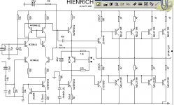
thanks for the compliments sir,
so sorry may be for the word "design" , I rather say "refered to " and calaculate for my own. Well, being a newbee in this real electronic
forum, I'm really very proud that you guys are there to share something with.
Sir Carlos:
can you share with me a schematic diagram of an old
YAMAHA P2200 power amp?
to let you know there is this audiophile store here that clones and sells
this amp for about P17,000(pesos) Philippine money or about $310.00.
they are so boastful about there amp that they think they had the most powerful amp around. They do not share their schemes, they
erase some labels of some of the parts, this I don't know why ,
I think they're afraid they'l also be cloned and earn less or nothing.
regards.
Mac Webster
sp_bagnol@yahoo.com
(hienrich is my two year old son)
Mar, very good, to use your son name in forum tell me a lot about you.
And i like what i can see by that inform you passing me.
I have studie Psychology, and i do know the wonderfull meaning of what you make, using your son's name.
Love is the answer.
I like that, and will be enormous pleasure to help you.
We have a forum friend, called Matt, www.schematicsforfree.com
You can go there and download maximum of 10 Megabytes each time you go there....and you can return next week...but you can disconnect and connect again that your counter return to zero...and he know that very well..... he agree with that...good man this Matt.
Yes, he ask some cooperation, small cooperation to maintain the site....but give us freedom not to cooperate too...and not beeing bad!...good man he is.
Try to go the adress i am sending you...if negative to download the 3.3 Megabytes entire schematic and service manual, go to may personal adress that i will upload the PDF for you, with pleasure.
http://schforfree.seedhost.com/archive/?path=Audio/Products/Amplifiers-Power
My personal adress:
nanabrother@yahoo.com
regards, Marc Hienrich
Let me see the boy's picture please.... love is the answer...war is foolish.,
Carlos
- Status
- This old topic is closed. If you want to reopen this topic, contact a moderator using the "Report Post" button.
- Home
- Amplifiers
- Solid State
- Will sound reasonable?... this amplifier is amps lab cousin